NR_Mechanischer_Stopper.pdf - 第188页
Assembly Instructions PCB Stopper Sin gle Conveyor SIPLACE S-27HM / HS-60 / D4 / D3 / HF- / X-Series Edition 06/2007 188 14.2.2 Removing the conversion board cover O Unscrew the motor above the conversion boa rd in conve…
Assembly Instructions PCB Stopper Single Conveyor SIPLACE S-27HM / HS-60 / D4 / D3 / HF- / X-Series
Edition 06/2007
187
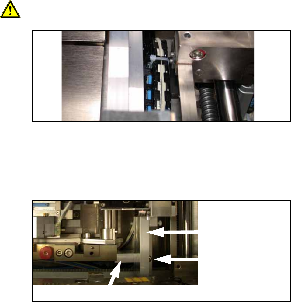
O Position the guide rail with the stoppers at its final position on the holders, but don't screw it
tight yet.
O Hold each of the trailing cable distance blocks in turn at the marked position with your hand
and check that the stoppers can move freely to the end.
14
Make sure that the trailing cable stands vertically to the stopper and does not collide with the belt
of the width adjustment. The stopper must subsequently move freely on the rail over the entire
conveyor width, and the trailing cables must not tilt to the side. 14
Fig. 163 Trailing cables
O When the trailing cables are in their final position, mark the exact positions of the trailing cable
distance blocks with a pen. Now stick the trailing cable distance blocks onto the marked posi-
tions with the double-sided adhesive tape. Make sure you keep the sticking surfaces clean and
do not touch them.
O Now affix the guide rail to the holders with two cylinder head bolts with hexagon socket head
M5 x 20 (DIN 912, ISO 4762).
Fig. 164 Attaching the guide rail (here: Conveyor track 1)
Guide rail
Screw for fixing the guide
rail to the holder (half hid-
den)
Holder
Assembly Instructions PCB Stopper Single Conveyor SIPLACE S-27HM / HS-60 / D4 / D3 / HF- / X-Series
Edition 06/2007
188
14.2.2 Removing the conversion board cover
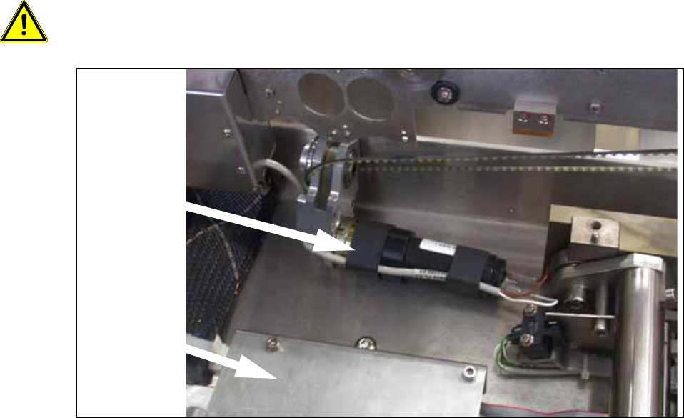
O Unscrew the motor above the conversion board in conveyor track 2 (3 hexagon screws) and
lay it to the side so that it doesn't get in the way when you are removing the conversion board
cover.
Caution: The three screws are of different lengths. Note the positions of the screws for when you
reinstall the motor later.
Fig. 165 Motor above the conversion board in conveyor track 2
Conversion
board cover
Motor
Assembly Instructions PCB Stopper Single Conveyor SIPLACE S-27HM / HS-60 / D4 / D3 / HF- / X-Series
Edition 06/2007
189
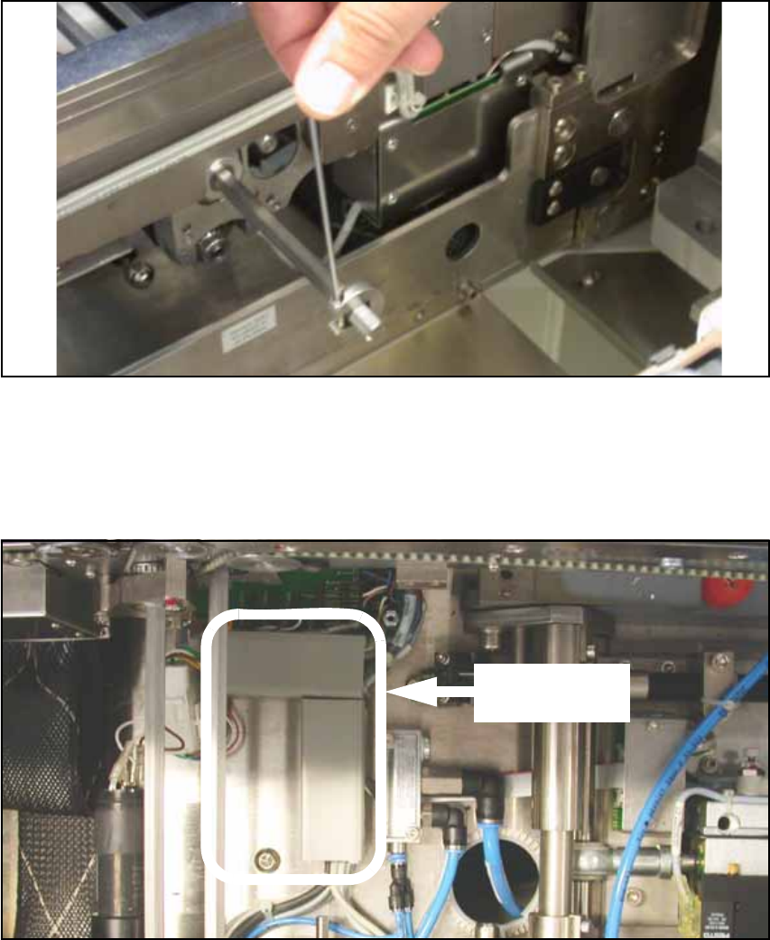
O In conveyor track 2 there is a shaft above the cover of the conveyor conversion board. Loosen
the shaft fixations on the outside of the lifting table and push the shaft into conveyor track 1.
Fig. 166 Shaft fixation
O Remove the cover of the conveyor conversion board.
14
O Remove the covers of the two cable ducts in conveyor track 1.
Fig. 167 Cable ducts (conveyor track 1)
Covers of cable
ducts