NR_Mechanischer_Stopper.pdf - 第190页
Assembly Instructions PCB Stopper Sin gle Conveyor SIPLACE S-27HM / HS-60 / D4 / D3 / HF- / X-Series Edition 06/2007 190 14.2.3 Cable and hose laying O Lay the bundled cables and hoses, st arting with the trailing cabl e…
Assembly Instructions PCB Stopper Single Conveyor SIPLACE S-27HM / HS-60 / D4 / D3 / HF- / X-Series
Edition 06/2007
189
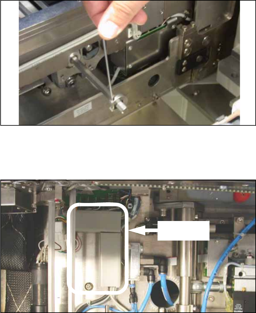
O In conveyor track 2 there is a shaft above the cover of the conveyor conversion board. Loosen
the shaft fixations on the outside of the lifting table and push the shaft into conveyor track 1.
Fig. 166 Shaft fixation
O Remove the cover of the conveyor conversion board.
14
O Remove the covers of the two cable ducts in conveyor track 1.
Fig. 167 Cable ducts (conveyor track 1)
Covers of cable
ducts
Assembly Instructions PCB Stopper Single Conveyor SIPLACE S-27HM / HS-60 / D4 / D3 / HF- / X-Series
Edition 06/2007
190
14.2.3 Cable and hose laying
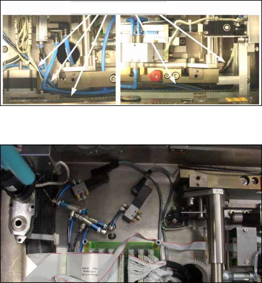
O Lay the bundled cables and hoses, starting with the trailing cable, under the belt for the width
adjustment. Using self-adhessive cable clamps, secure the cables parallel to the cables al-
ready running there, so that they don't touch the belt.
Route the cables back out from under the belt of the width adjustment at the height of the cable
ducts.
Fig. 168 Cable laying
O Place the pneumatic valves next to the conversion board in conveyor track 2. Shorten the
hoses to a reasonable length.
Fig. 169 Pneumatic valves
Cable laying (from right to left)
Assembly Instructions PCB Stopper Single Conveyor SIPLACE S-27HM / HS-60 / D4 / D3 / HF- / X-Series
Edition 06/2007
191
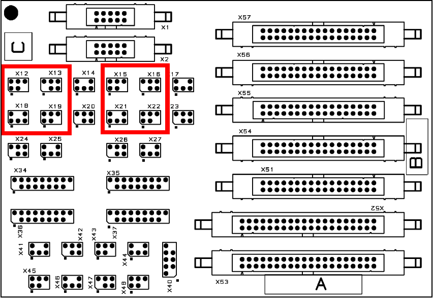
O Plug all the connectors (1 sensor, 1 sonar proximity switch, 1 solenoid valve and 1 bridge for
each conveyor track) onto the conversion board.
Fig. 170 Terminal plan for conversion board