NR_Mechanischer_Stopper.pdf - 第193页
Assembly Instructions PCB Stopper Single Conveyor SIPLACE S-27HM / HS-60 / D4 / D 3 / HF- / X-Series Edition 06/2007 193 before installation after installation O Connect the fee d line for the pneumatic valves to the con…
Assembly Instructions PCB Stopper Single Conveyor SIPLACE S-27HM / HS-60 / D4 / D3 / HF- / X-Series
Edition 06/2007
192
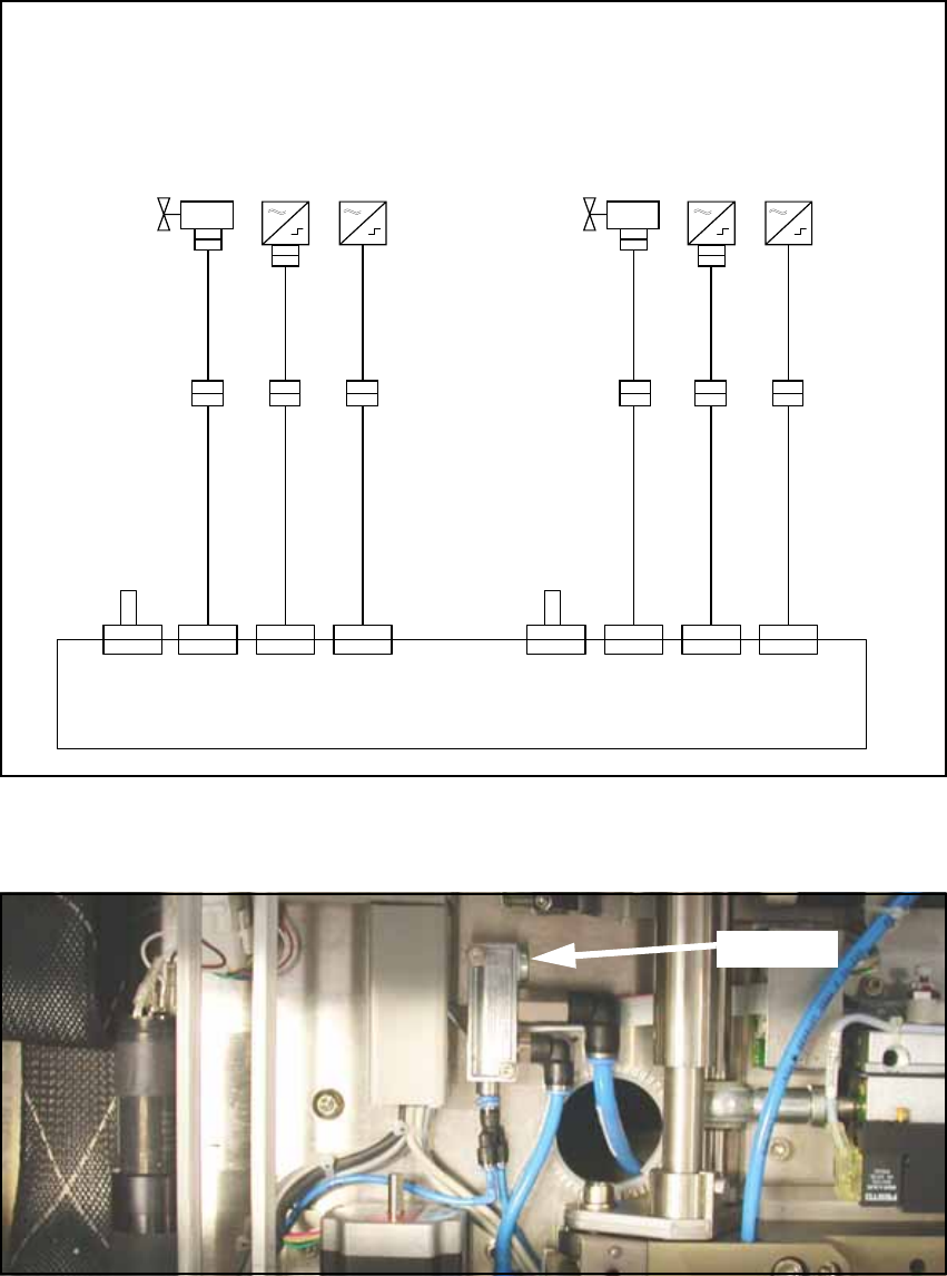
Fig. 171 Cabling of optional PCB stopper (S27)
O Detach the blind plug from the pneumatic distributor.
Fig. 172 Supply hose
X 1 9 / 2 2
U m s e t z p l a t i n e T r a n s p o r t
C o n v e r s i o n b o a r d c o n v e y o r
0 0 3 5 9 4 2 6 - x x ( k t )
X 1 9 k t
S o n a r b e r o
S o n a r s e n s o r
0 3 0 3 2 8 7 3 - x x
S e n s o r u n t e r e P o s i t i o n
S e n s o r l o w e r p o s i t i o n
V e n t i l
V a l v e
0 3 0 3 7 8 6 1 - x x
0 3 0 3 7 8 6 0 - x x
T r a n s p o r t s p u r 1 T r a n s p o r t s p u r 2 ( n u r b e i D o p p e l t r a n s p o r t )
0 3 0 3 7 8 5 9 - x x
X 1 3 / 1 6
X 1 3 k t
X 1 8 / 2 1
X 1 8 k t
X 2 2 k t
0 3 0 3 7 8 6 1 - x x
0 3 0 3 7 8 6 0 - x x
0 3 0 3 7 8 5 9 - x x
X 1 6 k tX 2 1 k t
X 1 9 / 2 2X 1 3 / 1 6X 1 8 / 2 1
X 1 2 / 1 5
X 1 5 k t
C o d i e r b r ü c k e " S t o p p e r S p u r 1 e i n g e b a u t "
C o d i n g j u m p e r " S t o p p e r l a n e 1 i n s t a l l e d "
X 1 2 / 1 5
X 1 2 k t
0 3 0 3 7 8 6 2 - x x
X a
X a
X b
X b
0 3 0 5 3 5 6 3 - x x
0 3 0 5 3 5 6 2 - x x
X a
X a
X b
X b
0 3 0 5 3 5 6 3 - x x
0 3 0 5 3 5 6 2 - x x
X c X c
X d
X d
0 3 0 5 6 1 5 7 - x x
X d
X d
0 3 0 5 6 1 5 7 - x x
C o n v e y o r l a n e 1 C o n v e y o r l a n e 2 ( d u a l c o n v e y o r o n l y )
V e n t i l
V a l v e
S o n a r b e r o
S o n a r s e n s o r
0 3 0 3 2 8 7 3 - x x
S e n s o r u n t e r e P o s i t i o n
S e n s o r l o w e r p o s i t i o n
C o d i e r b r ü c k e " S t o p p e r S p u r 2 e i n g e b a u t "
C o d i n g j u m p e r " S t o p p e r l a n e 2 i n s t a l l e d "
0 3 0 3 7 8 6 2 - x x
Blind plug
Assembly Instructions PCB Stopper Single Conveyor SIPLACE S-27HM / HS-60 / D4 / D3 / HF- / X-Series
Edition 06/2007
193
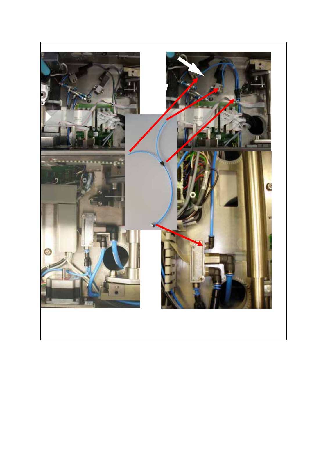
before installation after installation
O Connect the feed line for the pneumatic valves to the conveyor pneumatic distributor as shown
in the following figure.
Fig. 173 Installation of the feed line for the pneumatic valves
Assembly Instructions PCB Stopper Single Conveyor SIPLACE S-27HM / HS-60 / D4 / D3 / HF- / X-Series
Edition 06/2007
194
14.3 Concluding work
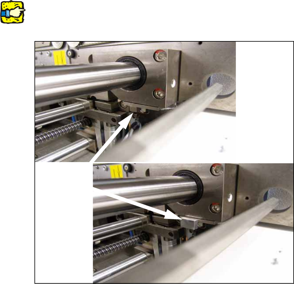
O Clean the adhesive surfaces for the distance pieces with a lint-free cloth moistened with ethyl
alcohol.
O Stick the distance pieces [03040724-xx] onto the limit switch actuator on the conveyor side with
the available adhesive tape. The limit switch is located on conveyor sides 2 and 4 at the junc-
tion to the output.
14
14
14
This distance piece prevents the conveyor sides from coming within 52 mm of each other and so
prevents the PCB conveyor and the stoppers from being damaged. 14
14
Fig. 174 Position to stick distance piece
Stick here