NR_Mechanischer_Stopper.pdf - 第194页
Assembly Instructions PCB Stopper Sin gle Conveyor SIPLACE S-27HM / HS-60 / D4 / D3 / HF- / X-Series Edition 06/2007 194 14.3 Concluding work O Clean the adhesive sur faces for the distan ce piec es with a lint-free clot…
Assembly Instructions PCB Stopper Single Conveyor SIPLACE S-27HM / HS-60 / D4 / D3 / HF- / X-Series
Edition 06/2007
193
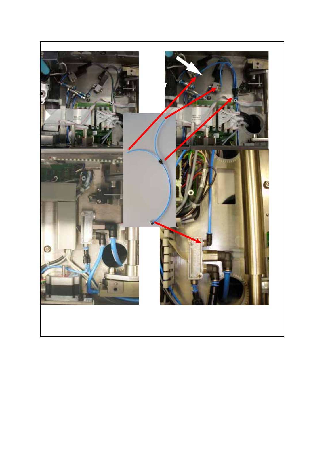
before installation after installation
O Connect the feed line for the pneumatic valves to the conveyor pneumatic distributor as shown
in the following figure.
Fig. 173 Installation of the feed line for the pneumatic valves
Assembly Instructions PCB Stopper Single Conveyor SIPLACE S-27HM / HS-60 / D4 / D3 / HF- / X-Series
Edition 06/2007
194
14.3 Concluding work
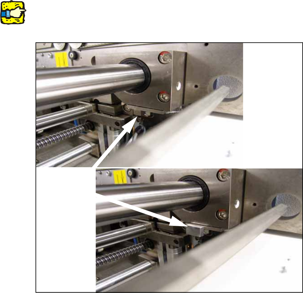
O Clean the adhesive surfaces for the distance pieces with a lint-free cloth moistened with ethyl
alcohol.
O Stick the distance pieces [03040724-xx] onto the limit switch actuator on the conveyor side with
the available adhesive tape. The limit switch is located on conveyor sides 2 and 4 at the junc-
tion to the output.
14
14
14
This distance piece prevents the conveyor sides from coming within 52 mm of each other and so
prevents the PCB conveyor and the stoppers from being damaged. 14
14
Fig. 174 Position to stick distance piece
Stick here
Assembly Instructions PCB Stopper Single Conveyor SIPLACE S-27HM / HS-60 / D4 / D3 / HF- / X-Series
Edition 06/2007
195
O Fit all the cable duct covers.
O Fit the cover of the conversion board.
O Install the motor in conveyor track 2 again (3 hexagon screws).
Note the different screw lengths (short at the top, long at the bottom) and make sure the toothed
belt is correctly seated.
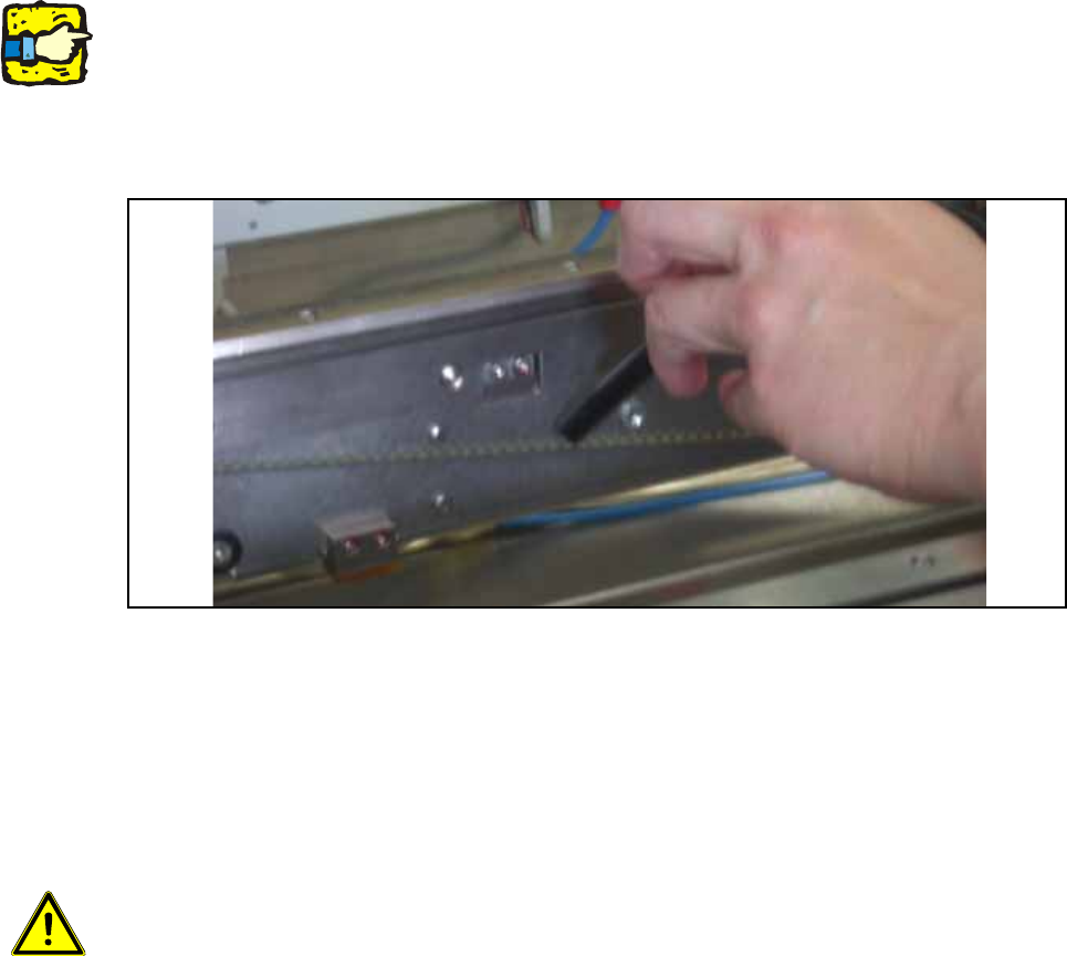
O Check whether the toothed belt has the correct tension of 110 +/- 5 Hz . Correct the tension if
necessary.
Fig. 175 Check belt tension
O Push the shaft back into conveyor track 2 and fit the corresponding shaft fixation on the outside
of the lifting table.
O Install the shortened lifting table plates on the lifting table.
O Dock the changeover tables again.
14
Caution: Crash hazard!
Check whether there are any objects left in the machine! Remove them.
O Switch on the placement machine at the main switch.
O Change to SITEST.
O Perform the settings according to:
"Setting the sonar proximity switches on the stopper" see section 16 on page - 221 14
"Software configuration and testing of the stopper" see section 18 on page - 227 14
14