NR_Mechanischer_Stopper.pdf - 第202页
Assembly Instructions PCB Stopper Sin gle Conveyor SIPLACE S-27HM / HS-60 / D4 / D3 / HF- / X-Series Edition 06/2007 202 15.1.2 Preparation of pneumatics O Det ach the supply hose (P UN 4) for width adjustment. Fig. 181 …
Assembly Instructions PCB Stopper Single Conveyor SIPLACE S-27HM / HS-60 / D4 / D3 / HF- / X-Series
Edition 06/2007
201
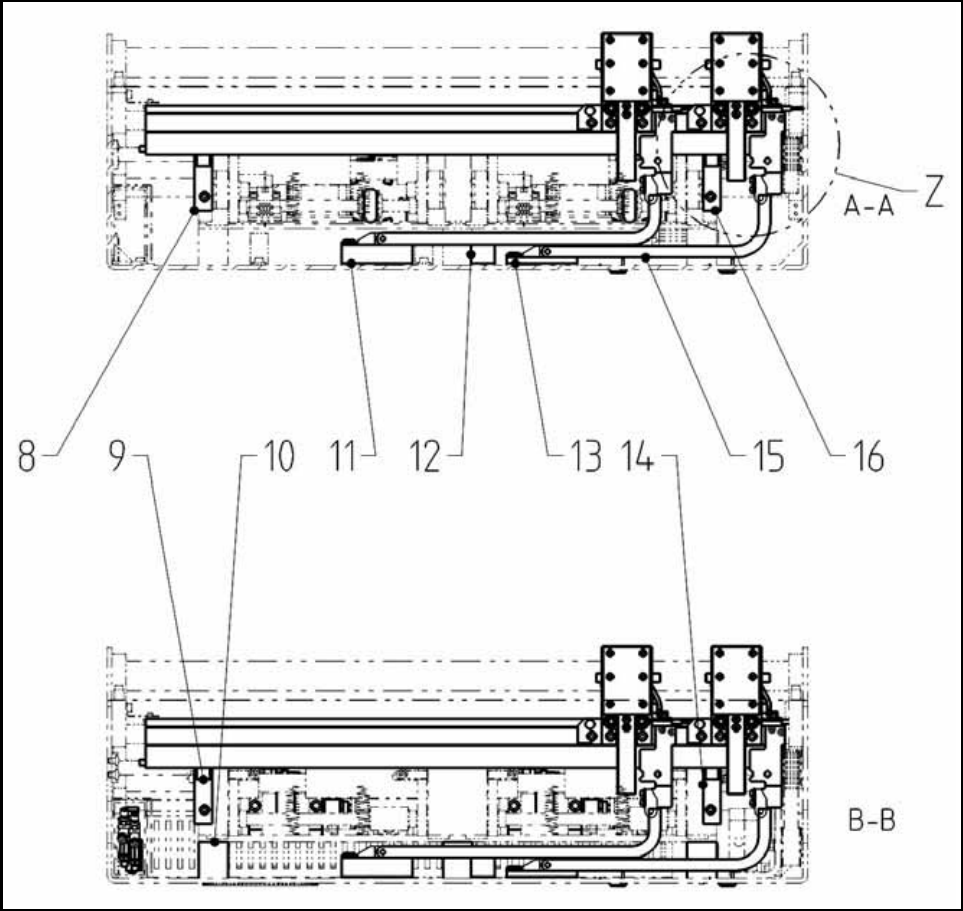
Fig. 180 Overview HF-/X-Series/D3 (Fig. 4) Dual conveyor
Legend (Figs. 3 and 4) Dual conveyor 15
1
Lifting table plate Option Stopper HF DC SP2
9
Distance block for energy chain, compl.
2
Lifting table plate Option Stopper HF DC SP1
10
Energy chain E04
3
Basic unit stopper HS/HF PA1
11
Guide strip HF
4
Basic unit stopper HS/HF PA2
12
ISO 4762 - M5 x 20-8.8, chem. nickel plat.
5
Holder for guide strip PA1 HF
13
ISO 4762 - M4 x 40-8.8, chem. nickel plat.
6
Holder for guide strip PA2 HF
14
DIN EN ISO 7380-M3 x 6-A2
7
Distance block for energy chain, compl.
15
Energy chain holder
8
Distance piece complete
16
ISO 4032 - M3-8
Assembly Instructions PCB Stopper Single Conveyor SIPLACE S-27HM / HS-60 / D4 / D3 / HF- / X-Series
Edition 06/2007
202
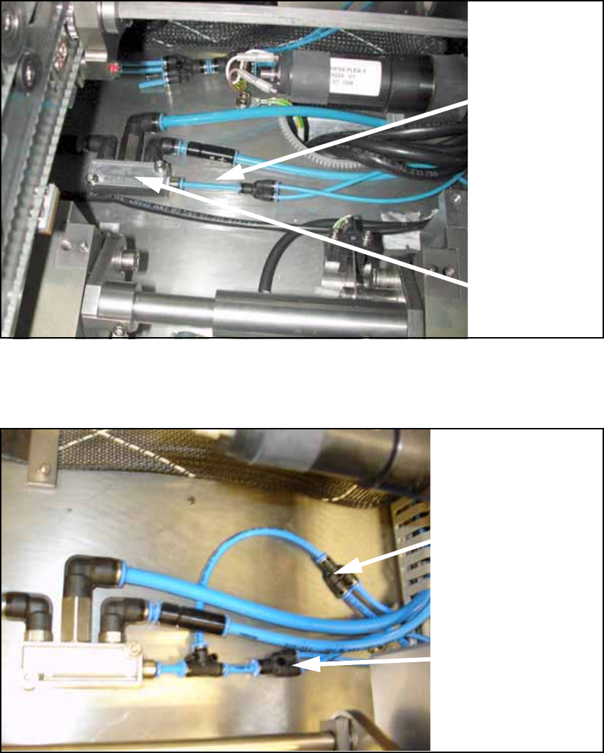
15.1.2 Preparation of pneumatics
O Detach the supply hose (PUN 4) for width adjustment.
Fig. 181
O Connect the prepared hoses to the conveyor pneumatic distributor as shown in the following
figure.
Fig. 182
Supply
hose (PUN 4)
for width
adjustment
Pneumatic
distributor
Supply hose (PUN 4)
for width adjustment
Supply hose (PUN 4)
for stopper unit
Assembly Instructions PCB Stopper Single Conveyor SIPLACE S-27HM / HS-60 / D4 / D3 / HF- / X-Series
Edition 06/2007
203
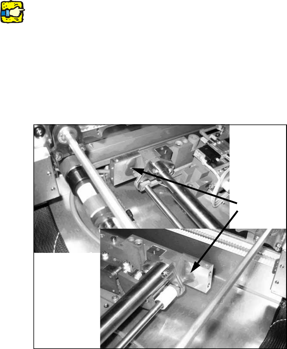
15.2 Installation at placement area 1
The surfaces on which the self-adhesive cable clamps, solenoid valves, etc., are to be stuck later
should be cleaned first with a lint-free cloth moistened with ethyl alcohol. 15
15
15.2.1 Installation of the holders
O Install the "Guide strip holders PA1 HF" [03032321-xx] (Fig. 183) for the guide strip of the PCB
stopper. The holders are installed so that they are flush at the top with the lateral frames of the
lifting table. To prevent the holder from twisting, the lateral shoulder of the holder must lie
against the outside of the frames.
Fasten each of the holders with a cylinder head bolt with hexagon socket head
M4 x 40-DIN 912.
Fig. 183 Holders
Holders