NR_Mechanischer_Stopper.pdf - 第228页
Assembly Instructions PCB Stopper Sin gle Conveyor SIPLACE S-27HM / HS-60 / D4 / D3 / HF- / X-Series Edition 06/2007 228 O After the rest art, change over to the SITEST Conveyor Functions. Here you ca n test the s toppe …
Assembly Instructions PCB Stopper Single Conveyor SIPLACE S-27HM / HS-60 / D4 / D3 / HF- / X-Series << >
Edition 06/2007 << >
227
18 Software configuration and testing of
the stopper
O Install the software version 505.03 or 601.03 or higher, if this has not already been done.
Use the corresponding software installation instructions for this.
18
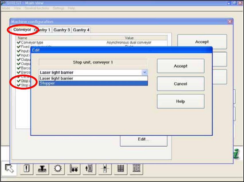
O Change over to the SITEST and in the "Machine configuration" menu activate the stopper for
every conveyor track by changing from "Laser light barrier" to "Stopper".
Fig. 204
A message is displayed that the machine has been reconfigured and is closing down. 18
O Confirm this message.
Assembly Instructions PCB Stopper Single Conveyor SIPLACE S-27HM / HS-60 / D4 / D3 / HF- / X-Series
Edition 06/2007
228
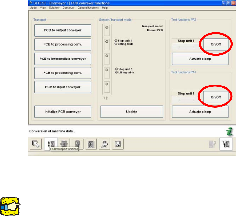
O After the restart, change over to the SITEST Conveyor Functions.
Here you can test the stoppers with the On/Off button.
O Test each stopper individually with the "On/Off" button.
Fig. 205
O Test the conveyor limit switch for each conveyor lane by reducing the width to 52mm.
18
18
18
Note: Check the correct cable laying and the correct pneumatic tubing to prevents the PCB con-
veyor and the stoppers from being damaged. 18
18
Assembly Instructions PCB Stopper Single Conveyor SIPLACE S-27HM / HS-60 / D4 / D3 / HF- / X-Series << >
Edition 06/2007 << >
229
18.1 Testing individual functions
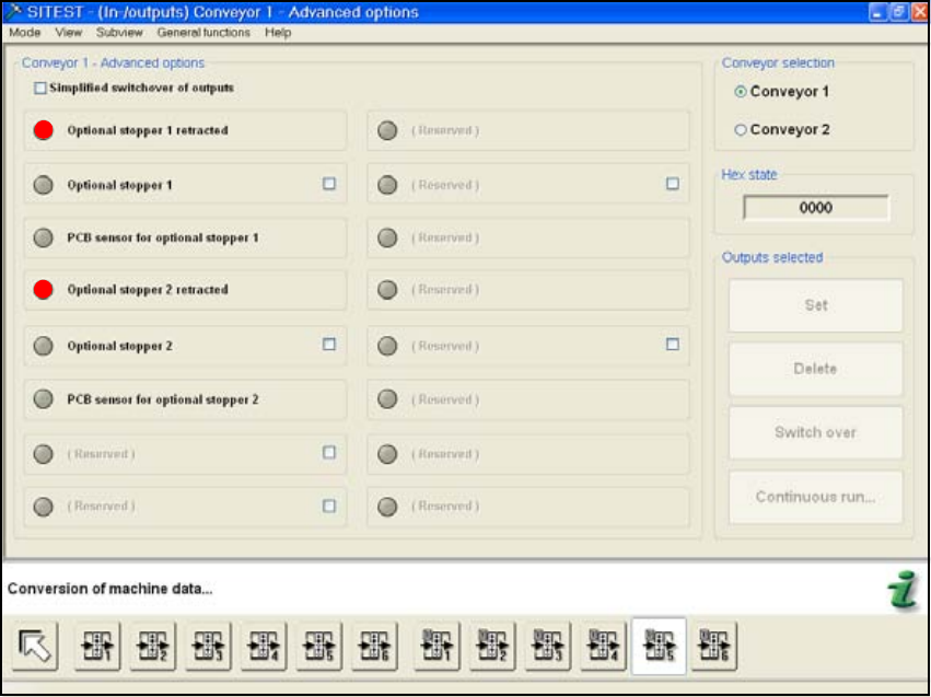
O Take a PCB and move it through each track of the PCB conveyor with the PCB conveyor func-
tions.
O You can check the status of the stopper in the window "Input/Output Functions 5".
Fig. 206
O Calibrate the machine zero point and the position of the nozzle changer (HS-60) also if neces-
sary.
O Finally, the PCB reference corner position needs to be recalibrated for each stop position.
18
18