NR_Mechanischer_Stopper.pdf - 第62页
Montageanleitung LP-Stopper Einfachtr ansport SIPLACE S-27HM / HS-60 / D4 / D3 / HF- / X-Serie Ausgabe 06/2007 62 3.5 Abschließende Arbeiten O Reinigen Sie die Kleb eflächen für die Distanzstücke mit e inem alkoholg eträ…
Montageanleitung LP-Stopper Einfachtransport SIPLACE S-27HM / HS-60 / D4 / D3 / HF- / X-Serie
Ausgabe 06/2007
61
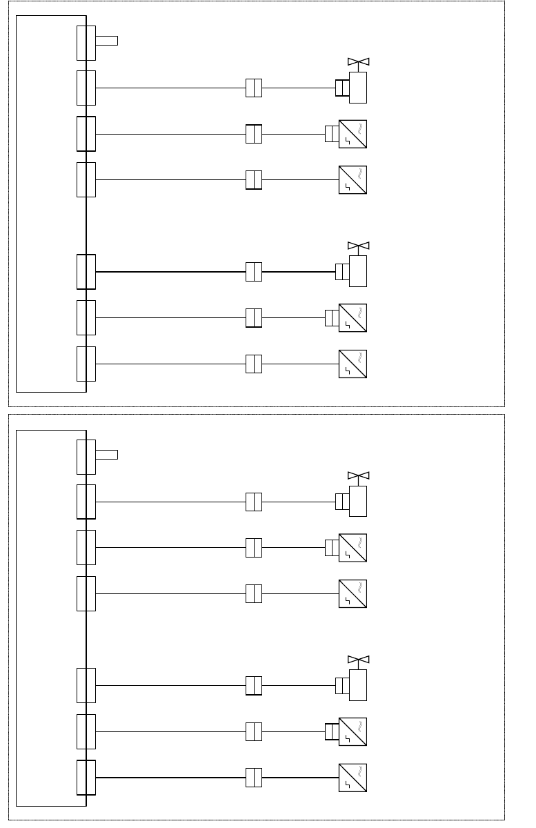
Abb. 46 Verkabelung optionaler LP-Stopper HS-60/D4/D3/HF-Serie/X-Serie
X 1 7
U m s e t z p l a t i n e T r a n s p o r t , S p u r 1
C o n v e r s i o n b o a r d c o n v e y o r , l a n e 1
0 0 3 5 9 4 2 5 - x x ( k t )
X 1 7 k t
0 3 0 3 7 1 9 4 - x x
0 3 0 3 7 1 9 6 - x x
T r a n s p o r t s p u r 1 / C o n v e y o r l a n e 1 T r a n s p o r t s p u r 2 ( n u r b e i D o p p e l t r a n s p o r t ) / C o n v e y o r l a n e 2 ( d u a l c o n v e y o r o n l y )
0 3 0 3 7 2 0 0 - x x
X 1 3
X 1 3 k t
X 3 0
X 3 0 k t
X 1 8 k t
0 3 0 3 7 1 9 5 - x x
0 3 0 3 7 1 9 7 - x x
0 3 0 3 7 2 0 1 - x x
X 1 5 k tX 3 3 k t
B e s t ü c k b e r e i c h 1
P r o c e s s i n g a r e a 1
B e s t ü c k b e r e i c h 2
P r o c e s s i n g a r e a 2
X 1 8X 1 5X 3 3 X 1 7
U m s e t z p l a t i n e T r a n s p o r t , S p u r 2
C o n v e r s i o n b o a r d c o n v e y o r , l a n e 2
0 0 3 5 9 4 2 5 - x x ( k u )
X 1 7 k u
0 3 0 3 7 1 9 4 - x x
0 3 0 3 7 1 9 6 - x x
0 3 0 3 7 2 0 0 - x x
X 1 3
X 1 3 k u
X 3 0
X 3 0 k u
X 1 8 k u
0 3 0 3 7 1 9 5 - x x
0 3 0 3 7 1 9 7 - x x
0 3 0 3 7 2 0 1 - x x
X 1 5 k uX 3 3 k u
X 1 8X 1 5X 3 3
X 6
X 6 k t
X 6
X 6 k u
0 3 0 3 7 2 0 4 - x x
0 3 0 3 7 2 0 4 - x x
X a
X a
X b
X b
X a
X a
X b
X b
X a
X a
X b
X b
X a
X a
X b
X b
0 3 0 5 3 5 6 3 - x x
0 3 0 5 3 5 6 2 - x x
0 3 0 5 3 5 6 3 - x x
0 3 0 5 3 5 6 2 - x x
0 3 0 5 3 5 6 3 - x x
0 3 0 5 3 5 6 2 - x x
0 3 0 5 3 5 6 3 - x x
0 3 0 5 3 5 6 2 - x x
X c
X c X c X c
X d
X d
X d
X d
0 3 0 5 6 1 5 7 - x x
0 3 0 5 6 1 5 7 - x x
X d
X d
0 3 0 5 6 1 5 7 - x x
X d
X d
0 3 0 5 6 1 5 7 - x x
B e s t ü c k b e r e i c h 1
P r o c e s s i n g a r e a 1
B e s t ü c k b e r e i c h 2
P r o c e s s i n g a r e a 2
S o n a r b e r o
S o n a r s e n s o r
0 3 0 3 2 8 7 3 - x x
S e n s o r u n t e r e P o s i t i o n
S e n s o r l o w e r p o s i t i o n
V e n t i l
V a l v e
S o n a r b e r o
S o n a
r s e n s o r
0 3 0 3 2 8 7 3 - x x
S e n s o r u n t e r e P o s i t i o n
S e n s o r l o w e r p o s i t i o n
V e n t i l
V a l v e
S o n a r b e r o
S o n a r s e n s o r
0 3 0 3 2
8 7 3 - x x
S e n s o r u n t e r e P o s i t i o n
S e n s o r l o w e r p o s i t i o n
V e n t i l
V a l v e
S o n a r b e r o
S o n a r s e n s o r
0 3 0 3 2 8 7 3 - x x
S e n s o r
u n t e r e P o s i t i o n
S e n s o r l o w e r p o s i t i o n
V e n t i l
V a l v e
C o d i e r b r ü c k e " S t o p p e r S p u r 1 e i n g e b a u t "
C o d i n g j u m p e r " S t o p p e r l a n e 1 i n s t a l l e d "
C o d i e r b r ü c k e " S t o p p e r
S p u r 1 e i n g e b a u t "
C o d i n g j u m p e r " S t o p p e r l a n e 1 i n s t a l l e d "
Montageanleitung LP-Stopper Einfachtransport SIPLACE S-27HM / HS-60 / D4 / D3 / HF- / X-Serie
Ausgabe 06/2007
62
3.5 Abschließende Arbeiten
O Reinigen Sie die Klebeflächen für die Distanzstücke mit einem alkoholgetränkten fusselfreien-
Tuch.
O Kleben Sie die Distanzstücke [03040724-xx] mit dem vorhandenen Klebeband an die Trans-
portwange auf den Betätiger Endschalter. Dieser befindet sich im Bestückbereich 1 an der
Wange 2 und 4 am Übergang der Ein-/Ausgabeseiten.
3
3
3
HINWEIS: Dieses Distanzstück verhindert ein Zusammenfahren der Transportwangen auf unter
52 mm und somit eine Beschädigung des LP-Transports bzw. der Stopper. 3
3
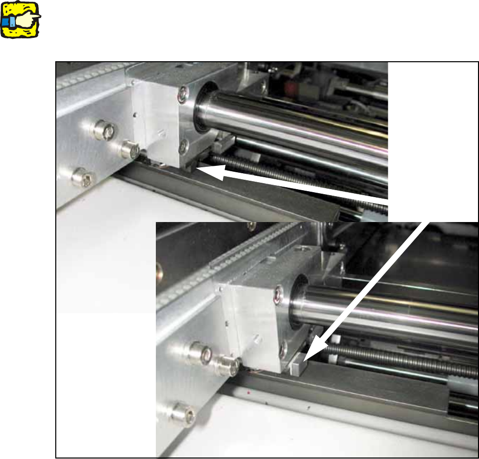
Abb. 47 Klebeposition Distanzstück
Klebeposition

Montageanleitung LP-Stopper Einfachtransport SIPLACE S-27HM / HS-60 / D4 / D3 / HF- / X-Serie
Ausgabe 06/2007
63
O Fixieren Sie alle Kabel mit selbstklebenden Kabelschellen und Kabelbindern.
O Montieren Sie die Kabelkanalabdeckungen.
O Montieren Sie die Blechabdeckung über dem Kabelkanal (Stellplatz 2).
O Montieren Sie die geänderte „Abdeckung Umsetzplatine Option Stopper“ [03041584-xx].
O Montieren Sie, sofern zuvor demontiert, den Halter Maschinennullpunkt und die Pipetten-
wechsler.
O Montieren Sie die Hubtischplatten für den Optionalen Stopper:
ACHTUNG: Crashgefahr!
Überprüfen Sie, ob noch Gegenstände in der Maschine liegen! Entfernen Sie diese.
O Schalten Sie den Bestückautomaten am Hauptschalter ein.
O Wechseln Sie in den SITEST.
O Kalibrieren Sie ggf. die ausgebauten Pippetenwechsler und den Maschinennullpunkt bei Dop-
peltransportmaschinen
O Führen Sie die Einstellungen durch gemäß:
"Einstellen der Sonarberos am Stopper" siehe Abschnitt 6 auf Seite - 107 3
"Software-Konfiguration und Test des Stoppers" siehe Abschnitt 8 auf Seite - 113 3
3
Hubtischplatte Op. Stopper HS DT BB1 SP1 [03041540-xx]
Hubtischplatte Op. Stopper HS DT BB1 SP2 [03041541-xx]
Hubtischplatte Op. Stopper HS DT BB2 SP1 [03041542-xx]
Hubtischplatte Op. Stopper HS DT BB2 SP2 [03041543-xx]
Hubtischplatte Opt. Stopper HS ET BB1 [03036007-xx]
Hubtischplatte Opt. Stopper HS ET BB2 [03036934-xx]