00193875-01.pdf - 第34页
3 Graphical user interface SIPLA CE Software Guide Version 101.xx 3.3 User interface - views and menus Issue 05/03 EN 34 NOTE The next two menu options belo ng to the group of vision funct ions. These functions are use d…

SIPLACE Software Guide Version 101.xx 3 Graphical user interface
Issue 05/03 EN 3.3 User interface - views and menus
33
NOTE
The following 3 menu options belong to the group of single functions.
The single functions are used to execute specific actions following fatal errors as well as to set up
and test the machine since they allow you to address the various functional modules in a defined
manner. 3
SF gantry 1 F5 3
This is used to call the single functions for gantry 1. These can be used to, for example, test the
functions of the revolver head. 3
NOTE
Each of the two gantries can be addressed separately.
The functions are identical for both gantries. 3
SF gantry 2 F6 (only for SIPLACE CS) 3
Single functions for gantry 2 3
Conveyor 1 F7 3
This is used to call the single functions for PCB conveyor. These are used to test and set the func-
tional modules for PCB conveyor as well as to set the conveyor width. 3
3 Graphical user interface SIPLACE Software Guide Version 101.xx
3.3 User interface - views and menus Issue 05/03 EN
34
NOTE
The next two menu options belong to the group of vision functions.
These functions are used to teach and test fiducials, measure components and change compo-
nent package form data.
The vision functions cannot be executed at the "Operator" access level. 3
Teach fiducial F8 3
This menu item is used to call the functions for the processing of fiducials for PCB position recog-
nition.
For a more extensive description of the procedure refer to the "Vision functions" section of the op-
erating instructions and in the online Help system. 3
Test component F9 3
This menu item is used to call the functions for the processing of component package forms for
component centering.
For a more extensive description of the procedure refer to the "Vision Functions" section of the
operating instructions. 3
3
Start SITEST F10 3
This automatically starts the SITEST test program for machine set-up and calibration.
The user interface, together with the procedure for the execution of the functions, is described in
the separate User’s Manual for the SITEST test program. 3
NOTE
The SITEST test program cannot be started from the "Operator" access level. 3
SIPLACE Software Guide Version 101.xx 3 Graphical user interface
Issue 05/03 EN 3.3 User interface - views and menus
35
3.3.2.4 "Options" menu
The "Options" menu is only available in the main view. This menu contains all the supplementary
functions. 3
Æ Click the required menu item and then make the appropriate settings or selections in the cor-
responding windows or dialog boxes.
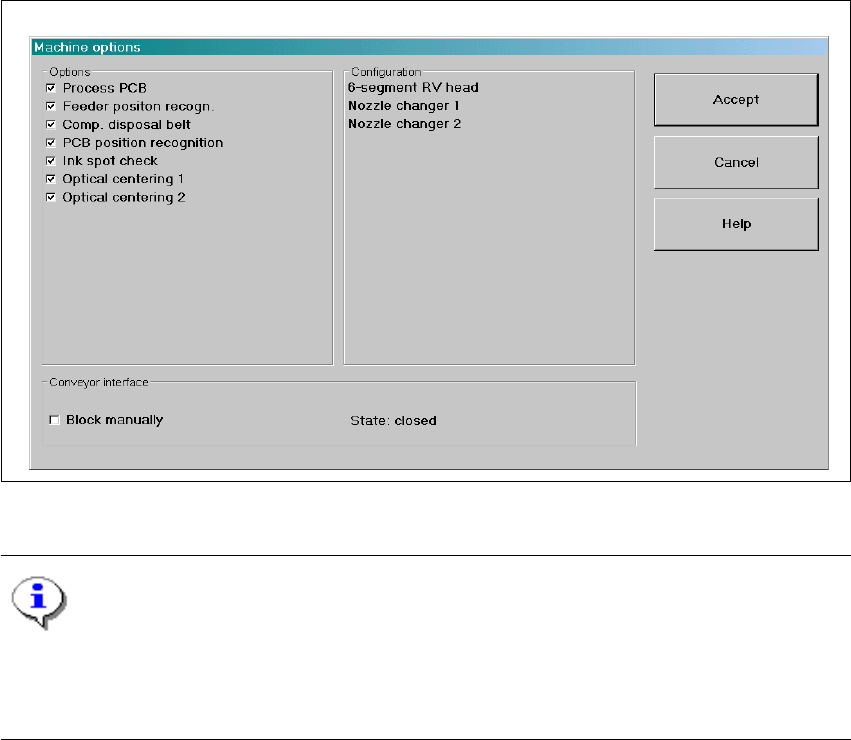
Machine options... 3
Depending on access level, you can obtain information about the station configuration ("Opera-
tor") or activate or deactivate the displayed machine options ("Line engineer", "Service"). 3
Æ Click the Machine options... menu item (or the appropriate button in the working area of the
main view). The following window is displayed.
3
Fig. 3.3 - 4 "Machine options" dialog box (example: SIPLACE CS)
NOTE
Only those machine options are displayed which are configured at the current station.
This dialog box may contain different information and check boxes depending on the type of
SIPLACE machine being used. 3