00197790-01.pdf - 第8页
Installation Guide Ausgabe 08/2014 Edition 8 ► Turn the m achine on. Make s ure that authorized staff check the equipment in operat ion to ensure that repairs were per formed correctl y. Testing Service personnel m ay te…
Installation Guide Ausgabe 08/2014 Edition
7
⇨ Shut down the station computer.
⇨ Switch the machine off at the main switch.
► Isolate the machine from all its energy sources:
⇨ Shut off the compressed air supply.
⇨ Shut off the main power supply.
► Lock out the machine.
⇨ Attach a lock wherever possible (e.g. to the main power switch or the motor contactor).
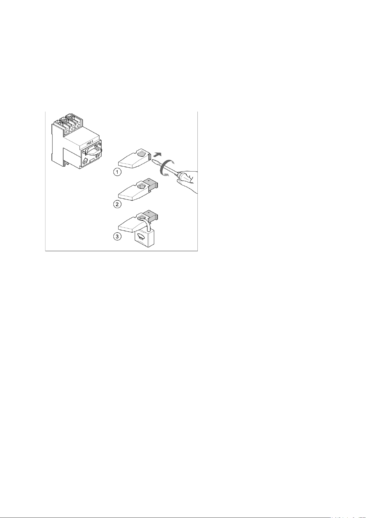
Example: attaching a padlock to the motor contactor
► Turn the operating lever (1) counterclockwise.
► Use the screwdriver to push the locking lug (2) out
of the operating lever (1).
► Secure the operating lever with a padlock (3).
► Alternative: attaching warning signs
If a machine can be locked, it must be. However, there are situations where energy isolating
devices cannot accommodate locks. In these cases, the energy isolating devices must be
tagged to warn employees that the machine is de-energized for servicing. The tag or label must
be securely fastened, it must be placed in a position visible to all and it may only be removed
by the person who attached it.
► Release of stored energy:
Stored energy in the compressed air supply or electrical energy in electrolytic capacitors must
be released by appropriate means.
⇨ After switching off the machine, wait until the voltages and the compressed air have
discharged, so that work can be performed without any risk.
► Testing the lock out:
The lock can be easily tested by pressing the START button.
► The following steps must be taken to restore the machine to operation.
► Check the working area. Authorized employees should remove all of their tools and reinstall all
safety features.
► Notify all affected employees.
► Before removing even one lock or tag, inform all workers in the affected area that the machine is
going to be restarted.
► Remove locks/tags
► Every authorized employee must remove his own lock and shut it away.

Installation Guide Ausgabe 08/2014 Edition
8
► Turn the machine on. Make sure that authorized staff check the equipment in operation to
ensure that repairs were performed correctly.
Testing
Service personnel may test circuits by energizing them briefly without suspending the Lock Out /
Tag Out Procedure. This may only be done when no other work is being performed by any other
person on the equipment being tested.
It is extremely important that all remote START switches be tagged with the "Do Not Operate" tag
to prevent inadvertent operation of the equipment during these periods.
Responsibilities
It shall be the responsibility of the maintenance and service personnel to make sure this
procedure is adhered to.
It shall be the responsibility of the maintenance and service personnel's immediate supervisor
to instruct his personnel on this procedure.
It shall be the responsibility of the Safety Officer with assistance from the Safety Committee,
Health Service Department, and the various managers and vice-presidents to administer the
Lock Out / Tag Out Procedure.
1.3 Scope of delivery
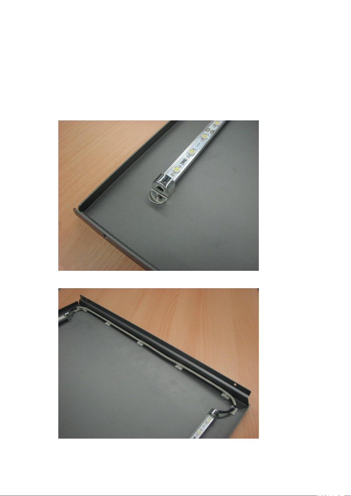
retrofitted central machine cover
2 LED-carriers with each 70 1W high power LEDs
Power supply 12V
2 auxillary switches
3 passing clamps grey
1 passing clamp blue
cables
11 Cable ties small
3 Cable ties medium
12 Cable tie base
Screws
Installation Guide Ausgabe 08/2014 Edition
9
2 Installation
2.1 LED-Carriers
mount the LED-carriers to the machine cover with the M3x10 flathead screws and poly stop
nuts. (drilling diameter 3.8mm)
(ATTENTION: Please consider the correct polarity 1 = + or brown = +)
stick the cable sockets to the machine cover