Galaxy EX Machine Control.pdf - 第2页
MACHINE CONTROL OVERVI EW 8.2 Tech nical Ref ere nce Ma nual Cha pter I ssue 4, Jun 18 The Next Mo ve E S card inco rpo rates a US B en code r/de code r and a C AN enc oder/ dec oder in terfac ing be twee n the P C and t…
MACHINE CONTROL
OVERVIEW
Chapter Issue 4, Jun 18 Technical Reference Manual 8.1
CHAPTER 8 MACHINE CONTROL
OVERVIEW
All machine functions are initiated by the ASM software installed on the PC.
The PC transmits and receives information to the NextMove ES card in the
M36 Machine Control Enclosure using a single USB lead. The NextMove ES
card incorporates its own processor which handles machine motions and
switch/sensor feedback, this frees up the PC processor to run the MMI and
other peripherals.
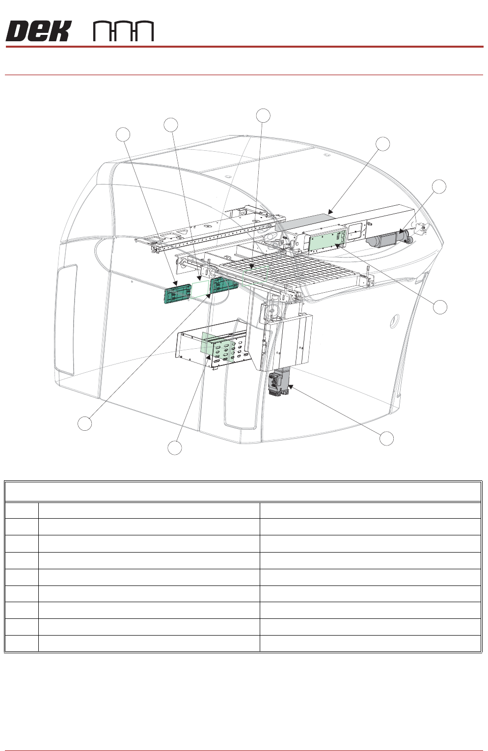
Machine Control Location Diagram
1 Servo Node 10 Paste Dispenser Motor
2 Servo Node 7 Print Carriage Motor
3 I/O Node Board 3 (behind panel) Print Carriage I/O
4 Servo Node 6 Rising Table Motor
5 I/O Node Board 1 (NextMove ES) Inside Machine Control Enclosure
6 I/O Node Board 4 Stencil Cleaner I/O
7 I/O Node Board 2 Main Machine I/O
8 I/O Node Board 5 Shared functionality OTS and HTC
9 I/O Node 19 TRS (Option)
MACHINE CONTROL
OVERVIEW
8.2 Technical Reference Manual Chapter Issue 4, Jun 18
The NextMove ES card incorporates a USB encoder/decoder and a CAN
encoder/decoder interfacing between the PC and the following:
• NextMove Interface Card
• Stepper Drive Cards
• EF Servo Drive Cards
• I/O Node Boards (via CAN Bus)
• Servo/Stepper Nodes (via CAN Bus)
NOTE
Following a service visit that involves any disturbance of components in the
mains voltage circuit an electrical test as detailed in the Pre Power Up section
of the Transportation chapter must be undertaken. Before testing ensure that
the machine is isolated from the factory supply and that any external
equipment (i.e. upline and downline conveyors) are disconnected.
CAUTION
ANTI-STATIC HANDLING.
Standard precautions must be adhered to when
handling electronic cards and configuring and inserting into the enclo-
sures.
NOTE
ASM recommends an antistatic wrist band that incorporates a 1 Meg ohm
resistor.
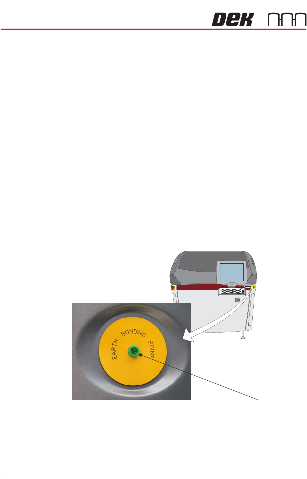
Figure 8-1 Antistatic Wrist Band Connection
ESD Connection
MACHINE CONTROL
ELECTRICAL SCHEMATIC
Chapter Issue 4, Jun 18 Technical Reference Manual 8.3
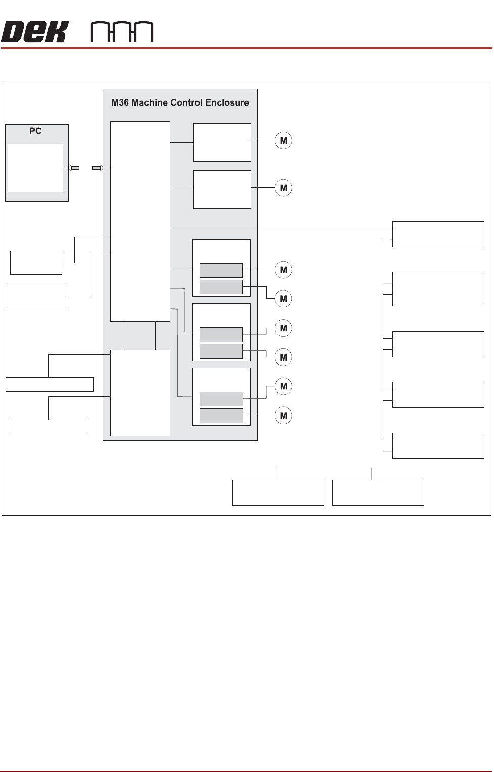
ELECTRICAL SCHEMATIC
NextMove
Interface
20 Digital Inputs
8 Digital Outputs
I/O Node 4 Board
(Screen Cleaner)
CAN Terminator
I/O Node 2 Board
(Main Machine)
Stepper Node 10
(Paste Dispense
Stepper Motor)
Servo Node 6
(Rising Table Motor)
Servo Node 7
(Print Carriage Motor)
I/O Node 3 Board
(Print Carriage)
USB
Motherboard
NextMove ES
(I/O Node 1)
4 Analogue
Outputs
2 Analogue
Inputs
Dual Stepper
Card X3
Step 2
Step 5
Dual Stepper
Card X2
Step 3
Step 4
Dual Stepper
Card X1
Step 0
Step 1
X Forward Actuator
Front Squeegee
YActuator
X Rear Actuator
Rear Squeegee
Moving Rail
I/Ps O/Ps
CAN Bus
EuroFlex
Card X6
Axis 0
Camera X Motor
Camera Y Motor
EuroFlex
Card X7
Axis 1