Galaxy EX Machine Control.pdf - 第3页
MACHINE CO NTROL EL EC T RIC AL SCH EM AT IC Ch apte r Issue 4, Jun 18 Tech nical Ref erenc e Ma nual 8.3 ELECTRICAL S CHEMA TI C NextMove Interface 20 Digital Inputs 8 Digital Outputs I/O Node 4 Board (Screen Cleaner) C…
MACHINE CONTROL
OVERVIEW
8.2 Technical Reference Manual Chapter Issue 4, Jun 18
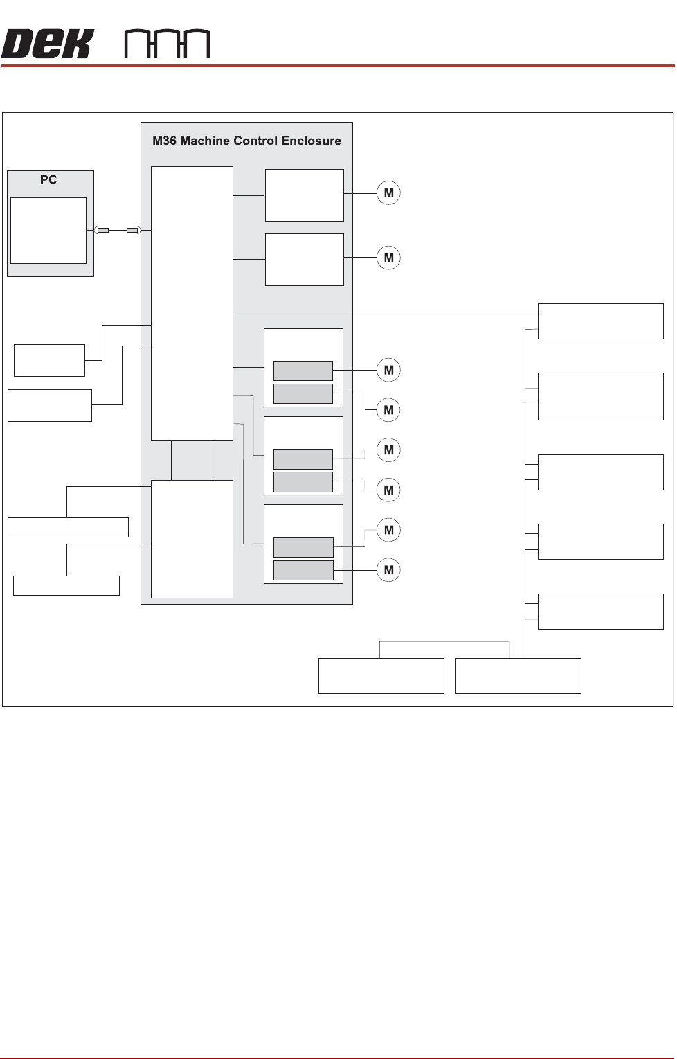
The NextMove ES card incorporates a USB encoder/decoder and a CAN
encoder/decoder interfacing between the PC and the following:
• NextMove Interface Card
• Stepper Drive Cards
• EF Servo Drive Cards
• I/O Node Boards (via CAN Bus)
• Servo/Stepper Nodes (via CAN Bus)
NOTE
Following a service visit that involves any disturbance of components in the
mains voltage circuit an electrical test as detailed in the Pre Power Up section
of the Transportation chapter must be undertaken. Before testing ensure that
the machine is isolated from the factory supply and that any external
equipment (i.e. upline and downline conveyors) are disconnected.
CAUTION
ANTI-STATIC HANDLING.
Standard precautions must be adhered to when
handling electronic cards and configuring and inserting into the enclo-
sures.
NOTE
ASM recommends an antistatic wrist band that incorporates a 1 Meg ohm
resistor.
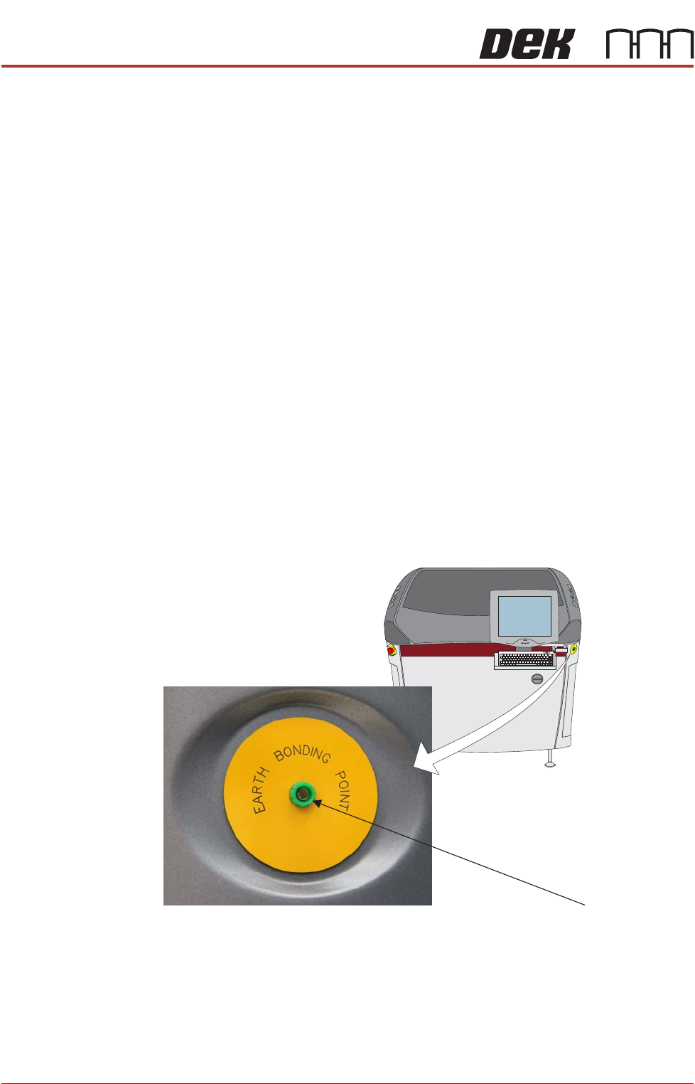
Figure 8-1 Antistatic Wrist Band Connection
ESD Connection
MACHINE CONTROL
ELECTRICAL SCHEMATIC
Chapter Issue 4, Jun 18 Technical Reference Manual 8.3
ELECTRICAL SCHEMATIC
NextMove
Interface
20 Digital Inputs
8 Digital Outputs
I/O Node 4 Board
(Screen Cleaner)
CAN Terminator
I/O Node 2 Board
(Main Machine)
Stepper Node 10
(Paste Dispense
Stepper Motor)
Servo Node 6
(Rising Table Motor)
Servo Node 7
(Print Carriage Motor)
I/O Node 3 Board
(Print Carriage)
USB
Motherboard
NextMove ES
(I/O Node 1)
4 Analogue
Outputs
2 Analogue
Inputs
Dual Stepper
Card X3
Step 2
Step 5
Dual Stepper
Card X2
Step 3
Step 4
Dual Stepper
Card X1
Step 0
Step 1
X Forward Actuator
Front Squeegee
YActuator
X Rear Actuator
Rear Squeegee
Moving Rail
I/Ps O/Ps
CAN Bus
EuroFlex
Card X6
Axis 0
Camera X Motor
Camera Y Motor
EuroFlex
Card X7
Axis 1
MACHINE CONTROL
M36 MACHINE CONTROL ENCLOSURE
8.4 Technical Reference Manual Chapter Issue 4, Jun 18
M36 MACHINE CONTROL ENCLOSURE
The M36 Machine Control Enclosure is located at the rear of the machine and
interfaces between the PC and machine motors, sensors and switches. The
PC connects to the M36 with a USB cable allowing two-way communications
between the two enclosures.
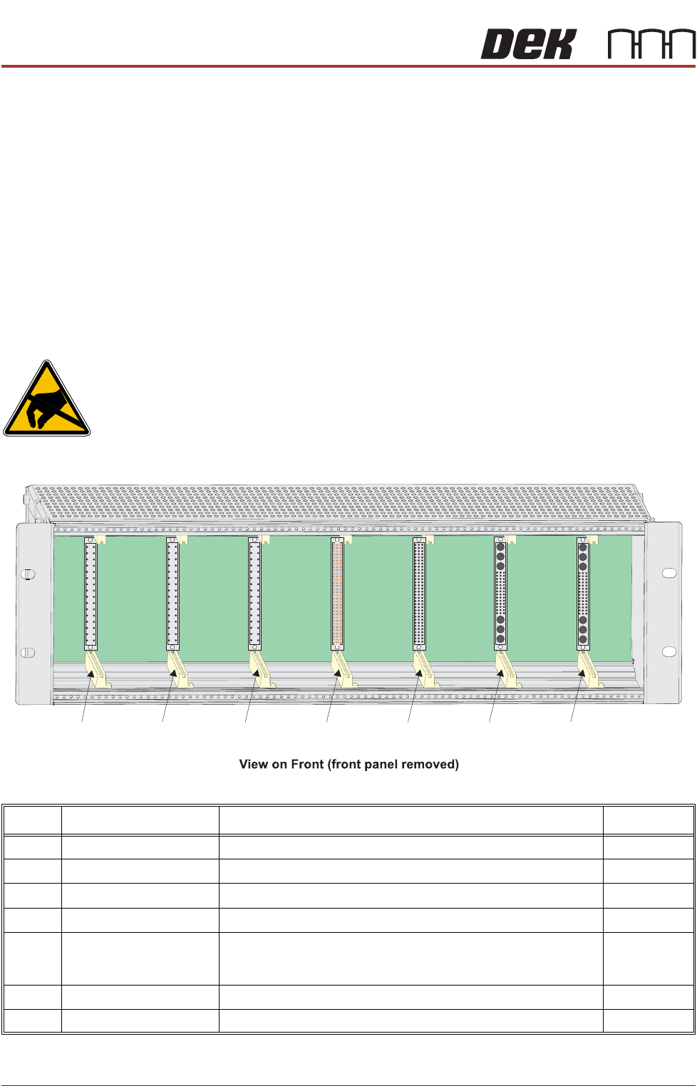
The M36 enclosure has a single backplane PCB with edge connectors
mounted on one side for plug-in cards (Slot X1 - X7) and plugs and sockets on
the other side, protruding through the rear panel, for connection to the
machine looms.
The front panel has a cut-out slot to allow connection of the USB and CAN Bus
cables to the NextMove ES card in Slot X5.
M36 Card Locations
CAUTION
ANTI-STATIC HANDLING. STANDARD PRECAUTIONS MUST BE ADHERED TO
WHEN HANDLING ELECTRONIC CARDS AND CONFIGURING AND INSERTING
INTO THE ENCLOSURES.
Slot Card Function Step/Axis
X1 Dual Stepper X Forward and X Rear Actuators Step 0,1
X2 Dual Stepper Front and Rear Squeegees Step 3,4
X3 Dual Stepper Y Actuator and Moving Rail Step 2,5
X4 NextMove Interface Opto-isolates 20 inputs and 8 outputs from the NextMove ES card
X5 NextMove ES
(I/O Node1)
Motion control card providing 6 stepper and 2 servo axes with real
time I/O. Also acts as a CAN master interfacing between the USB
and CAN buses
X6 EF Servo Drive Camera X Linear Servo Motor Axis 0
X7 EF Servo Drive Camera Y Linear Servo Motor Axis 1
Slot X1 Slot X2 Slot X3 Slot X4 Slot X5 Slot X6 Slot X7