Galaxy EX Machine Control.pdf - 第7页
MACHINE CO NTROL M36 MACHINE CONTROL E N CLOSURE Ch apte r Issue 4, Jun 18 Tech nical Ref erenc e Ma nual 8.7 Ne xtM ove E S Ed ge Co nnec tor The e dge co nnector con nects the ca r d to the b ackplane of the enclosu r …
MACHINE CONTROL
M36 MACHINE CONTROL ENCLOSURE
8.6 Technical Reference Manual Chapter Issue 4, Jun 18
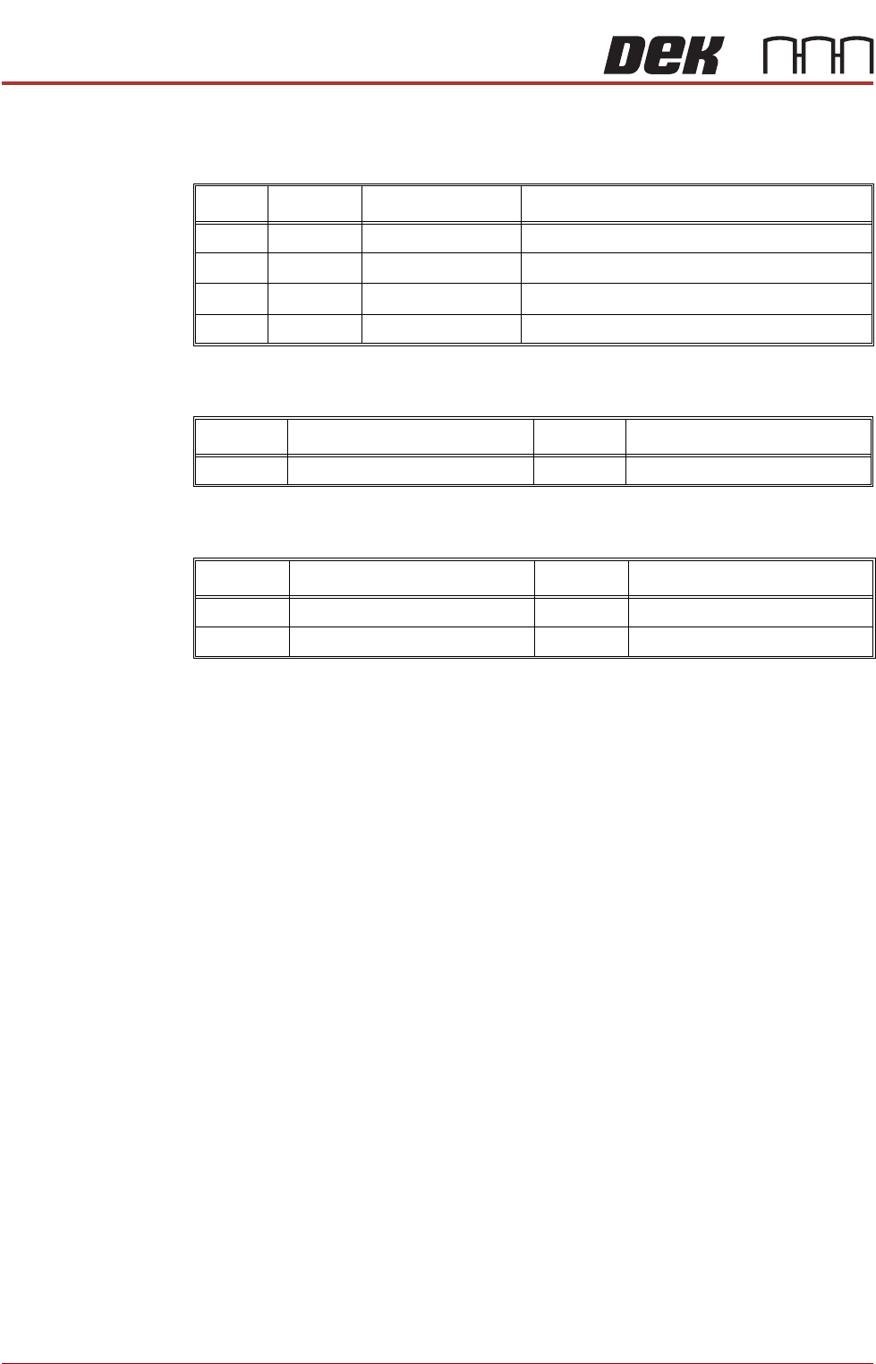
There are four surface mount LEDs on the board which are detailed in the
table below, NextMove ES Card figure refers:
Inputs The table below details the 2 analogue inputs:
Outputs The table below details the 4 analogue outputs:
LED Colour Normal Operation Purpose
D3 Yellow Off Indicates that the FPGA is being initialized
D4 Red Off Indicates that the card is in hardware reset
D16 Green Flashing Flashes at 0.5Hz to indicate firmware heartbeat
D20 Orange On Toggles on with reception of comms packet
Input Function Input Function
AIN0 USC Solvent Level AIN1 Spare
Output Function Output Function
AOUT0 Camera X AOUT2 Spare
AOUT1 Camera Y AOUT3 Temperature Output to TCM
MACHINE CONTROL
M36 MACHINE CONTROL ENCLOSURE
Chapter Issue 4, Jun 18 Technical Reference Manual 8.7
NextMove ES Edge
Connector
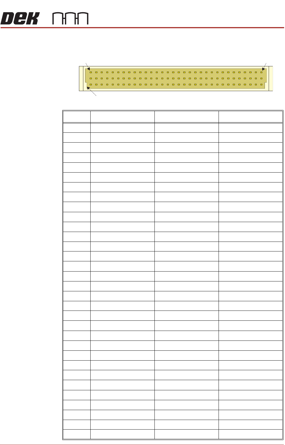
The edge connector connects the card to the backplane of the enclosure.
Pin No. Row a Row b Row c
1 +5.5V +5.5V +5.5V
2 +5.5V +5.5V +5.5V
3 DGND DGND DGND
4 OUT COM DOUT7 DOUT6
5 DOUT5 DOUT4 DOUT3
6 DOUT2 DOUT1 DOUT0
7 Encoder 0 CHB Encoder 0 CHA Encoder 1 CHB
8 Encoder 1 CHA Encoder 0 Index Encoder 1 Index
9 Encoder 1!Index Encoder 0!Index Encoder 1!CHA
10 Encoder 1!CHB Encoder 0!CHA Encoder 0!CHB
11 DGND Error Out DIN16
12 DGND DGND !RST IN
13 STEP4 DIR4 DGND
14 STEP0 STEP1 STEP2
15 DIR0 DIR1 DIR2
16 RSVD DGND STEP5
17 RSVD AOUT2 DGND
18 DIN2 DIN15 DIN4
19 DIN7 DIN5 DIN3
20 RXD DIN1 DIN6
21 TXD RTS DIN0
22 CTS AOUT3 DIR5
23 DIR3 STEP3 DIN14
24 DIN10 DIN13 DIN17
25 DIN11 DIN9 DIN18
26 DIN8 DIN19 DIN12
27 AIN1- Demand1 (AOUT1) Demand0 (AOUT0)
28 AIN0- AIN0+ AIN1+
29 +12V DC +12V DC +12V DC
30 AGND AGND AGND
31 -12V DC -12V DC -12V DC
32 Shield Shield Shield
a
b
c
1 32
Keyway
MACHINE CONTROL
M36 MACHINE CONTROL ENCLOSURE
8.8 Technical Reference Manual Chapter Issue 4, Jun 18
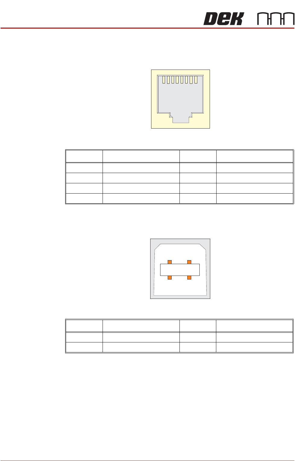
CAN Connector The CAN connector is an RJ45 socket connecting the NextMove card to the
various CAN Node boards and CAN Servo/Stepper motors throughout the
machine.
Figure 8-3 CAN Bus Connector
USB Connector The USB connector is a Type B socket used to connect the NextMove ES card
to the PC.
Figure 8-4 USB Type B Connector
Pin No. Signal Pin No. Signal
1 CAN+ 5 +24V
2CAN- 6N/C
3N/C 7N/C
40V 8N/C
1
8
Pin No. Signal Pin No. Signal
1 +5.5V 3 Data+
2 Data- 4 0V
12
3
4