Galaxy EX Machine Control.pdf - 第8页
MACHINE CONTROL M36 MACHINE CONTROL E N CLOSURE 8.8 Tech nical Ref ere nce Ma nual Cha pter I ssue 4, Jun 18 CAN Connector Th e CA N connector is an RJ45 s ocket connecting the NextMove card to the vari ous CA N N ode bo…
MACHINE CONTROL
M36 MACHINE CONTROL ENCLOSURE
Chapter Issue 4, Jun 18 Technical Reference Manual 8.7
NextMove ES Edge
Connector
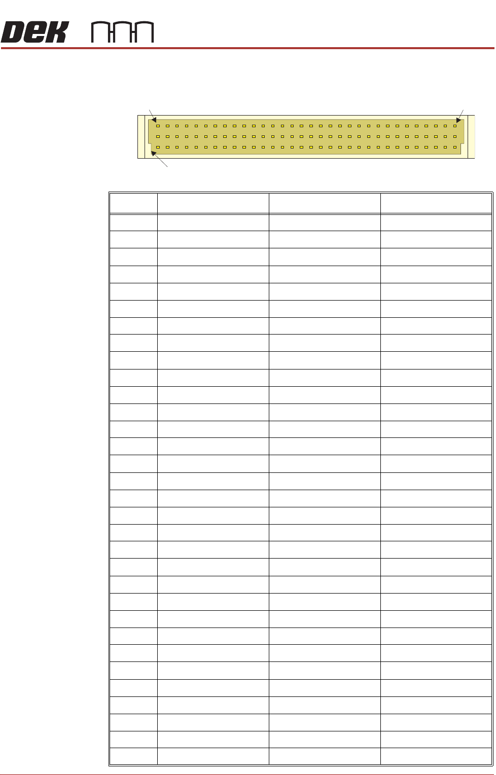
The edge connector connects the card to the backplane of the enclosure.
Pin No. Row a Row b Row c
1 +5.5V +5.5V +5.5V
2 +5.5V +5.5V +5.5V
3 DGND DGND DGND
4 OUT COM DOUT7 DOUT6
5 DOUT5 DOUT4 DOUT3
6 DOUT2 DOUT1 DOUT0
7 Encoder 0 CHB Encoder 0 CHA Encoder 1 CHB
8 Encoder 1 CHA Encoder 0 Index Encoder 1 Index
9 Encoder 1!Index Encoder 0!Index Encoder 1!CHA
10 Encoder 1!CHB Encoder 0!CHA Encoder 0!CHB
11 DGND Error Out DIN16
12 DGND DGND !RST IN
13 STEP4 DIR4 DGND
14 STEP0 STEP1 STEP2
15 DIR0 DIR1 DIR2
16 RSVD DGND STEP5
17 RSVD AOUT2 DGND
18 DIN2 DIN15 DIN4
19 DIN7 DIN5 DIN3
20 RXD DIN1 DIN6
21 TXD RTS DIN0
22 CTS AOUT3 DIR5
23 DIR3 STEP3 DIN14
24 DIN10 DIN13 DIN17
25 DIN11 DIN9 DIN18
26 DIN8 DIN19 DIN12
27 AIN1- Demand1 (AOUT1) Demand0 (AOUT0)
28 AIN0- AIN0+ AIN1+
29 +12V DC +12V DC +12V DC
30 AGND AGND AGND
31 -12V DC -12V DC -12V DC
32 Shield Shield Shield
a
b
c
1 32
Keyway
MACHINE CONTROL
M36 MACHINE CONTROL ENCLOSURE
8.8 Technical Reference Manual Chapter Issue 4, Jun 18
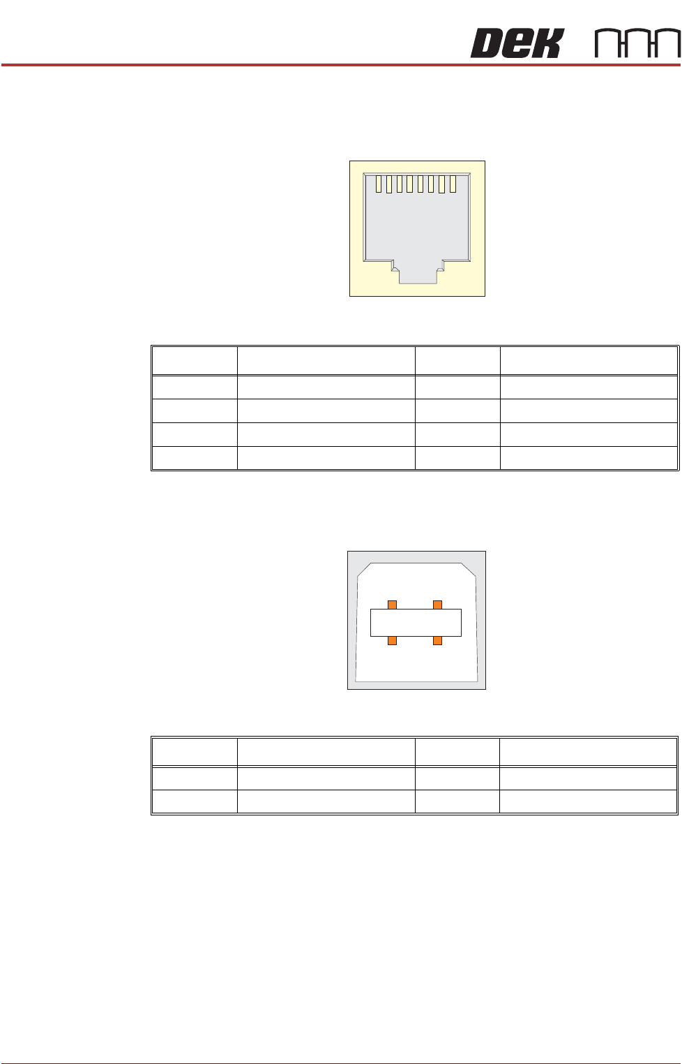
CAN Connector The CAN connector is an RJ45 socket connecting the NextMove card to the
various CAN Node boards and CAN Servo/Stepper motors throughout the
machine.
Figure 8-3 CAN Bus Connector
USB Connector The USB connector is a Type B socket used to connect the NextMove ES card
to the PC.
Figure 8-4 USB Type B Connector
Pin No. Signal Pin No. Signal
1 CAN+ 5 +24V
2CAN- 6N/C
3N/C 7N/C
40V 8N/C
1
8
Pin No. Signal Pin No. Signal
1 +5.5V 3 Data+
2 Data- 4 0V
12
3
4
MACHINE CONTROL
M36 MACHINE CONTROL ENCLOSURE
Chapter Issue 4, Jun 18 Technical Reference Manual 8.9
NextMove Interface Card
CAUTION
ANTI-STATIC HANDLING. STANDARD PRECAUTIONS MUST BE ADHERED TO
WHEN HANDLING ELECTRONIC CARDS AND CONFIGURING AND INSERTING
INTO THE ENCLOSURES.
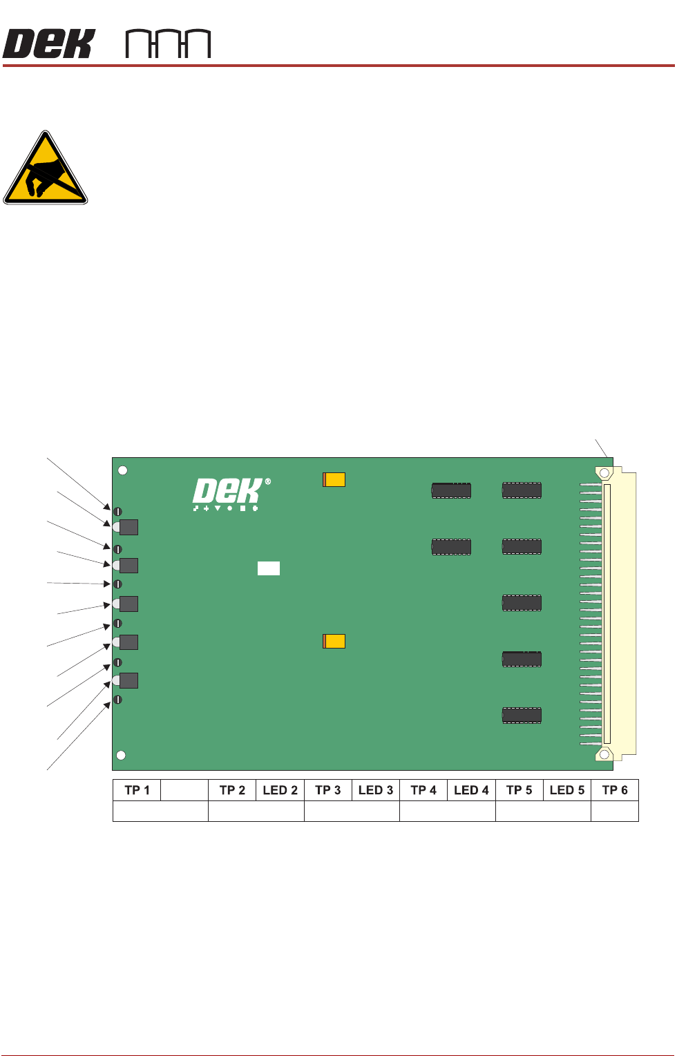
The NextMove Interface card opto-isolates 20 inputs and 7 outputs provided
by the NextMove ES card. Also provided is an Error Out which is used for the
Software E Stop power, this is not opto-isolated.
The card consists of 5 LEDs indicating voltages present and test points for
checking and aligning the voltages required.
NOTE
The voltages are adjusted in the M37 Power Supply Enclosure, Power Supply
and Distribution chapter refers.
Figure 8-5 NextMove Interface Card
96 Pin Edge Connector
185020 ISSUE
NEXTM O VE INTERFACE BOARD
TP 1
TP 3
TP 2
TP 4
TP 5
TP 6
LED 1
LED 1
LED 3
LED 2
LED 4
LED 5
24V US 24V SW
+12V -12V
+5.5V
DGND