192277 - Micron Technical Reference Volume 1.pdf - 第85页
View on Rear of Switch Switch Re l ease T oo l Switch Body Contact Assemb l y
COVERS
PRINTER COVERS
3.42 Technical Reference Manual Chapter Issue 11, Jan 17
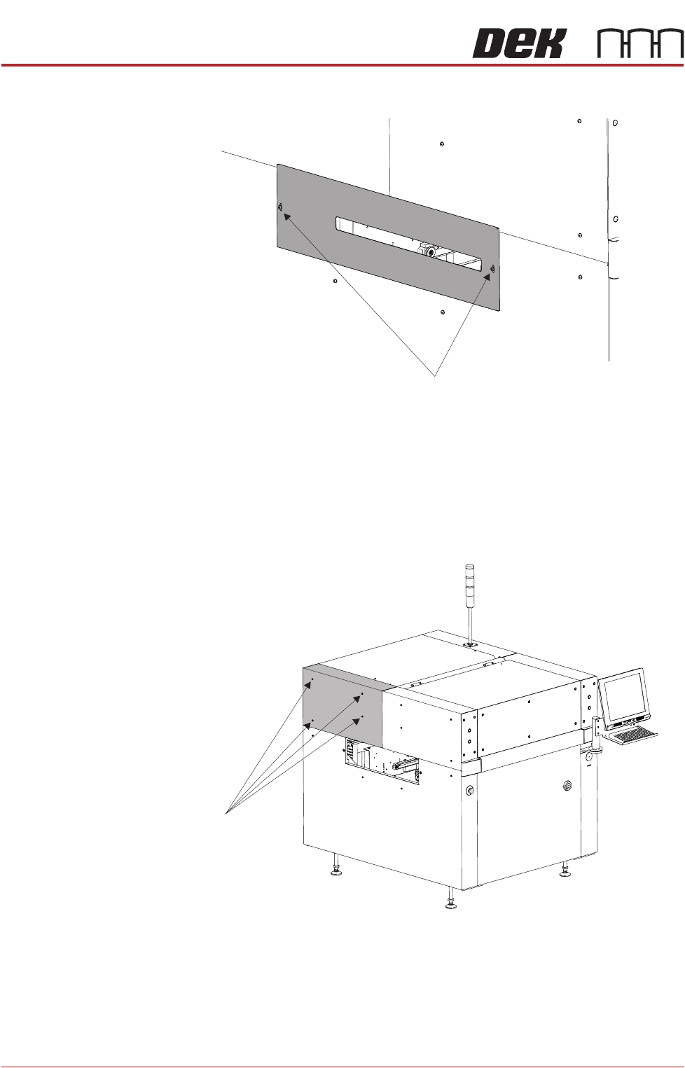
To remove the safety cover, remove the two securing screws.
Rear Corner Panels To remove the rear corner panels, carry out the following:
1. Remove the Left Hand Safety Cover (as detailed previously).
2. Remove the Right Hand Safety Cover (as detailed previously).
3. Using a 4mm Allen key, undo the appropriate four captive screws.
4. Lift the panel clear of the printer frame, taking care not to damage the earth
cable.
5. Repeat Steps 3 and 4 for the other rear corner panel, if required.
Safety Cover Securing Screws
Front Left Quarter View
Captive Screws
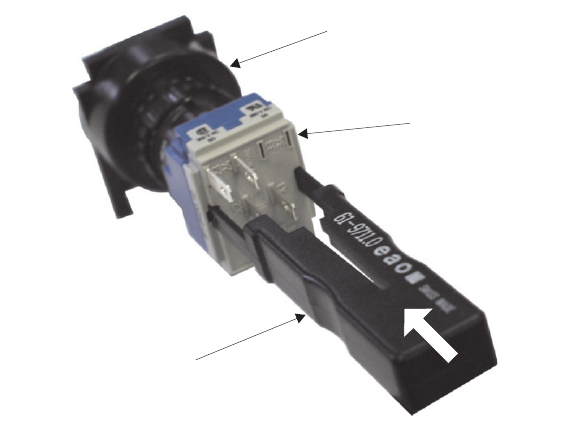
View on Rear of Switch
Switch Release Tool
Switch Body
Contact Assembly
COVERS
PRINTER COVERS
3.44 Technical Reference Manual Chapter Issue 11, Jan 17
NOTE
To refit the contact assembly to the switch body, using the locating
keyway, push the two units together until they click into place.
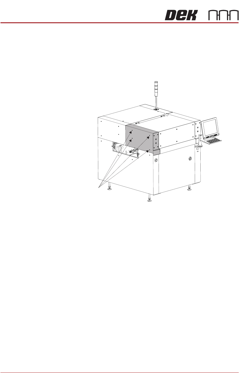
3. Using a 4mm Allen key, undo the appropriate four captive screws.
4. Remove the panel clear of the printer, taking care not to damage the earth
cable.
5. Repeat Steps 3 to 4 for the other upper front corner panel, if required.
Front Left Quarter View
Captive Screws