00194931-20 Anleitung CAN Test Box-Error Frame Diagnoseeinheit_de.pdf - 第52页
1 - 52 SIPLACE CAN Bus Ausgabe 10/2018 52 Abb. 4.5 - 1 1 CAN Bus Struktur ( ein CAN Bus HF mit Universalkabelbaum und KSP352)
1 - 51
Ausgabe 10/2018 Siplace CAN Bus
51
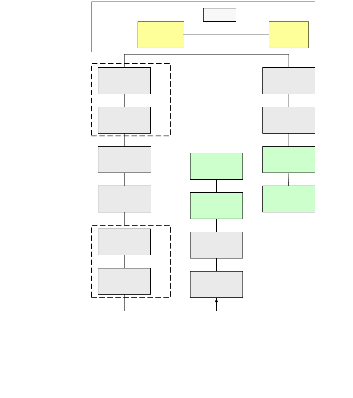
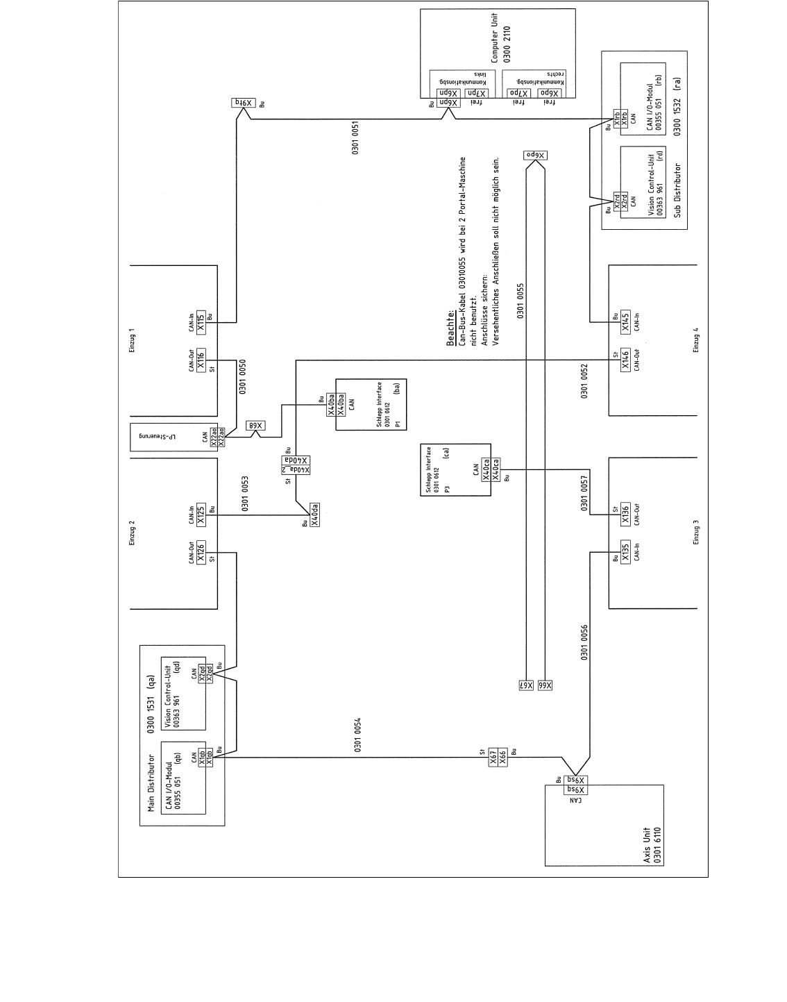
4.5.6 HF CAN Bus Struktur mit Universalkabelbaum KSP352 (SW 504)
CAN Bus Struktur mit SW 504.xx und Com Baugruppe KSP 352 mit Universalkabelbaum (Be-
schriftung am Kabel (0301xxxx-0x), ein CAN Bus für beide Bestückbereiche.
Abb. 4.5 - 10 CAN Bus Struktur ( ein CAN Bus HF mit Universalkabelbaum KSP 352)
SMP BUS
MC
Axis unit
PA 2
Trailing cable-
Interface
Portal 1
CAN Bus cable
COT 3
Tape cutter
Computer Unit
One CAN Bus!
* SW Update 504 --> 505 Gantry 2 will be changed to gantry 3
new trailling cable !
old circuit diagram!
Trailing cable-
Interface
Gantry 2 *
Transport
COT 2 / MTC
Tape cutter
CAN E/
A
Modu
l
Sektor
4
CAN E/
A
Modu
l
Sektor
4
CAN E/
A
Modu
l
Sektor
4
CAN I/O
SUB Module
Section 4
Vision
Control unit
COT 1
Tape cutter
COT 4 / MTC
Tape cutter
SUB Distributor Section 4
Vision
Section 2
CAN I/O
Main Module
Section 2
Main Distributor Section 2
Section 4
Control unit
Control unit
x6pn
Head board(C500)
Gantry 1
Terminator
(120 OHM)
Head board(C500)
Gantry 2*
Terminator
(120 OHM)
C
O
M
U
n
i
t
K
S
P
3
5
2
(
r
i
g
h
t
)
C
O
M
U
n
i
t
K
S
P
3
5
2
(
l
e
f
t
)
1 - 52
SIPLACE CAN Bus Ausgabe 10/2018
52
Abb. 4.5 - 11 CAN Bus Struktur ( ein CAN Bus HF mit Universalkabelbaum und KSP352)
1 - 53
Ausgabe 10/2018 Siplace CAN Bus
53
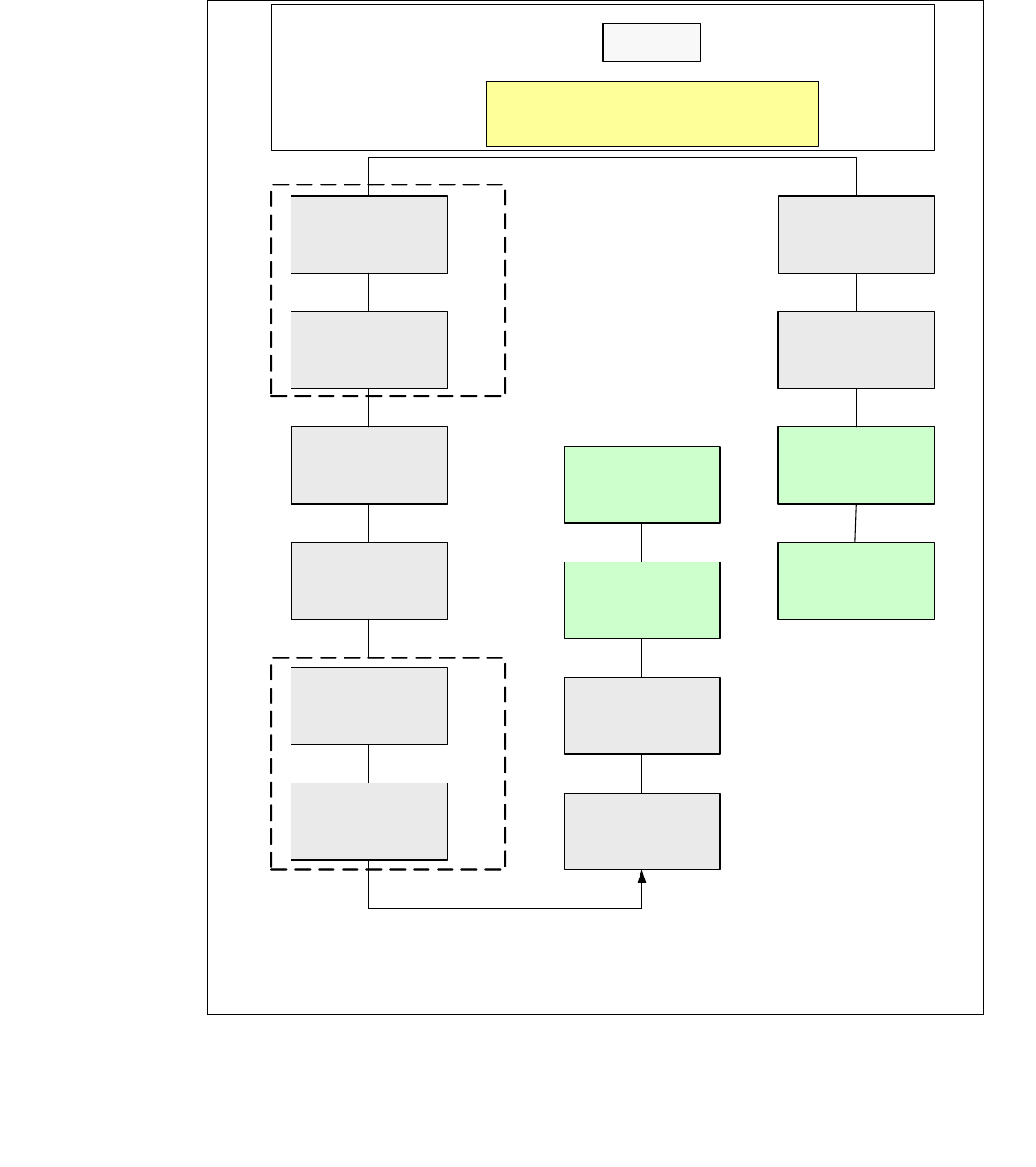
4.5.7 HF CAN Bus Struktur mit Universalkabelbaum KSP354 (SW 504)
CAN Bus Struktur mit SW 504.xx und Com Baugruppe KSP 354 mit Universalkabelbaum (Be-
schriftung am Kabel (0301xxxx-0x), ein CAN Bus für beide Bestückbereiche.
Abb. 4.5 - 12 CAN Bus Struktur ( ein CAN Bus HF mit Universlkabelbaum KSP 354)
SMP BUS
C
O
M
U
n
i
t
K
S
P
3
5
4
MC
Axis unit
PA 2
Trailing cable-
Interface
Portal 1
CAN Bus cable
COT 3
Tape cutter
Computer Unit
One CAN Bus!
* SW Update 504 --> 505 Gantry 2 will be changed to gantry 3
new trailling cable !
old circuit diagram!
Trailing cable-
Interface
Gantry 2 *
Transport
COT 2 / MTC
Tape cutter
CAN E/
A
Modu
l
Sektor
4
CAN E/
A
Modu
l
Sektor
4
CAN E/
A
Modu
l
Sektor
4
CAN I/O
SUB Module
Section 4
Vision
Control unit
COT 1
Tape cutter
COT 4 / MTC
Tape cutter
SUB Distributor Section 4
Vision
Section 2
CAN I/O
Main Module
Section 2
Main Distributor Section 2
Section 4
Control unit
Control unit
x6pn
Head board(C500)
Gantry 1
Terminator
(120 OHM)
Head board(C500)
Gantry 2*
Terminator
(120 OHM)