np134 mechanical reference-1.1e.pdf.pdf - 第100页
Procedure [Setting Example] Assume that the board has a slit which is 5 mm wide, and the conveyor speed is 360 mm/s. The time required for the slit to pass the sensor is therefore 14 ms (5/360). A delay time which exceed…
4. Adjustment
4.1 Adjusting the Conveyor Sensor Delay Times
Point
When conveying boards which have slits (such as multi-blok boards, etc.), the sensor
may mistake the slit for the edge of the board. To prevent this, the sensor delay time
should be adjusted. There are two sensor types: type “A” and type “B”.
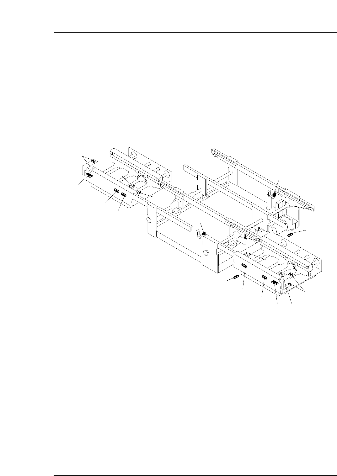
The sensor and amplifier unit configuration is shown below.
NP1MT002a
10
1
2
4
6
3
5
13
8
14
12
15
16
7
11
9
1. In-conveyor panel loading sensor
2. Amplifier unit (type "B") for in-conveyor panel loading sensor
3. In-conveyor panel arrival sensor
13. Out-conveyor panel arrival sensor
7. Main conveyor-1 panel arrival sensor
8. Timer unit (type "A") for main conveyor-1 panel arrival sensor
9. Main conveyor-2 panel arrival sensor
5. In-conveyor panel unloding sensor
6. Timer unit (type "A") for in-conveyor panel unloading sensor
10. Timer unit (type "A") for main conveyor-2 panel arrival sensor
4. Timer unit (type "A") for in-conveyor panel arrival sensor
14. Amplifier unit (type "A") for out-conveyor panel arrival sensor
15. Out-conveyor panel unloading sensor
11. Out-conveyor panel unloding sensor
12. Timer unit (type "A") for out-conveyor panel unloading sensor
16. Amplifier unit (type "B") for out-conveyor panel unloading sensor
Part 3 Chapter 4 Adjustment
Edition 1.0 3-4-1 NP-134E/134ME Mechanical
Procedure
[Setting Example]
Assume that the board has a slit which is 5 mm wide, and the conveyor speed is 360
mm/s. The time required for the slit to pass the sensor is therefore 14 ms (5/360).
A delay time which exceeds 14 ms is therefore required. To obtain this delay time, the
amplifier “B” setting should be specified as “0” (30±3 ms).
Note: Although the sensor delay time must be longer than the time required for the slit to pass the
sensor, do not specify a delay time which is longer than necessary as this may slow the
cycle time.
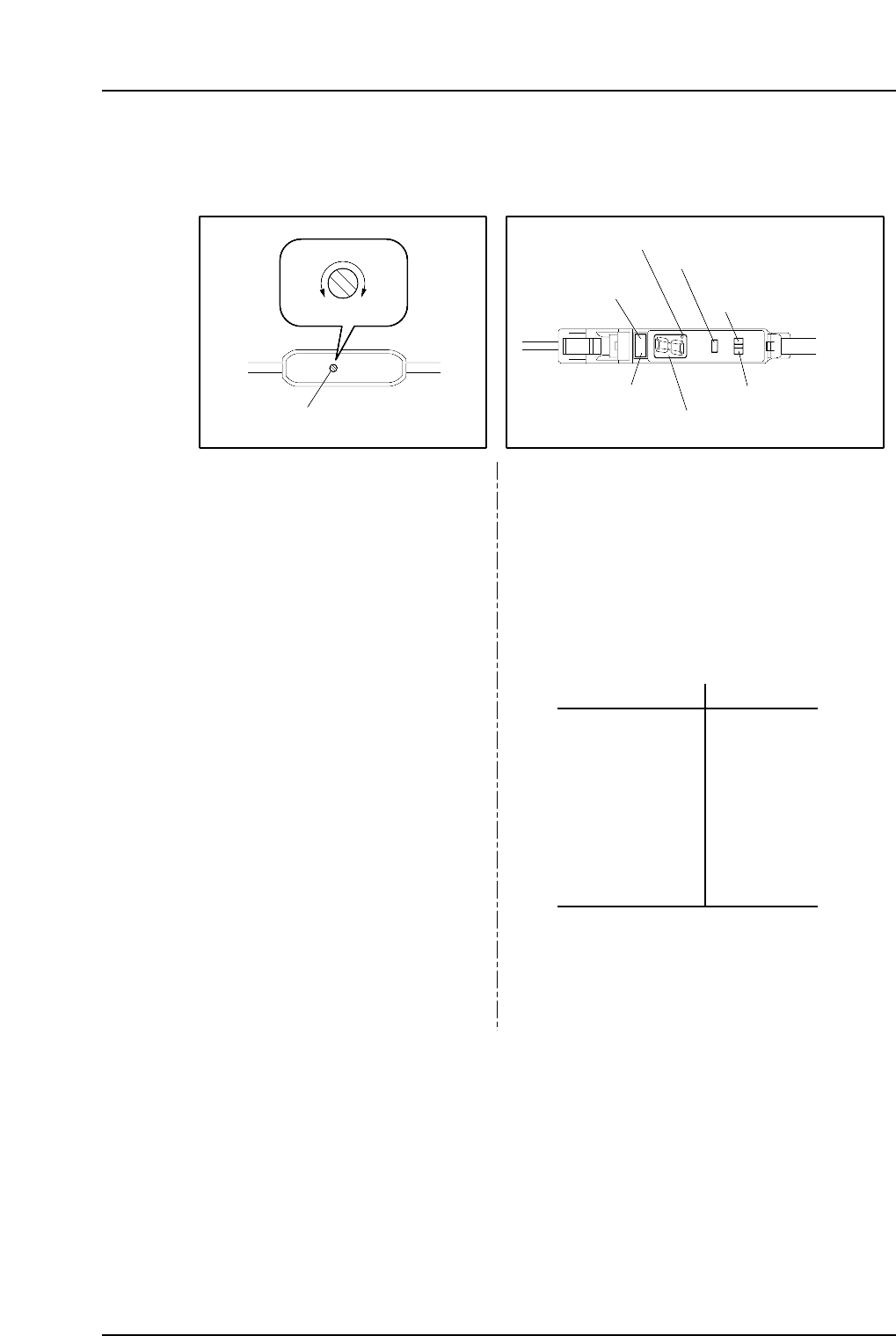
Delay time setting trimmer
MIN MAX
Type “A” Type “B”
NP1MT001
0
1
2
3
4
5
6
7
8
9
30±3 ms
100±10 ms
200±20 ms
300±30 ms
400±40 ms
500±50 ms
600±60 ms
700±70 ms
800±80 ms
1s±100 ms
SET
RUN
Delay time setting switch
Operation lamp
(red)
ON delay lamp
Tuning button
Mode selector switch
“Stable” lamp (green)
Digital display
Adjust the delay time by using a
screwdriver, etc., to turn the
trimmer.
1. Set the delay time setting switch to the SET
position.
The delay time (0~9 value) then displays at
the digital display.
2. Press the tuning button to select the desired
delay time. The delay time setting value
increases each time the button is pressed.
Setting range: 5 ~ 300 ms
Delay time display Setting time
3. Set the delay time setting switch to the RUN
position. The specified time (0~9 value) then
displays at the digital display.
Part 3 Chapter 4 Adjustment
Edition 1.0 3-4-2 NP-134E/134ME Mechanical

Part 4
Setup