np134 mechanical reference-1.1e.pdf.pdf - 第101页
Part 4 Setup
Procedure
[Setting Example]
Assume that the board has a slit which is 5 mm wide, and the conveyor speed is 360
mm/s. The time required for the slit to pass the sensor is therefore 14 ms (5/360).
A delay time which exceeds 14 ms is therefore required. To obtain this delay time, the
amplifier “B” setting should be specified as “0” (30±3 ms).
Note: Although the sensor delay time must be longer than the time required for the slit to pass the
sensor, do not specify a delay time which is longer than necessary as this may slow the
cycle time.
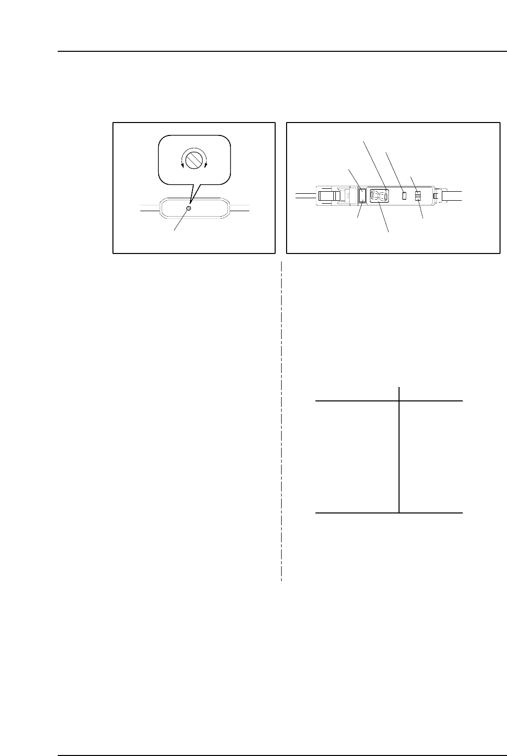
Delay time setting trimmer
MIN MAX
Type “A” Type “B”
NP1MT001
0
1
2
3
4
5
6
7
8
9
30±3 ms
100±10 ms
200±20 ms
300±30 ms
400±40 ms
500±50 ms
600±60 ms
700±70 ms
800±80 ms
1s±100 ms
SET
RUN
Delay time setting switch
Operation lamp
(red)
ON delay lamp
Tuning button
Mode selector switch
“Stable” lamp (green)
Digital display
Adjust the delay time by using a
screwdriver, etc., to turn the
trimmer.
1. Set the delay time setting switch to the SET
position.
The delay time (0~9 value) then displays at
the digital display.
2. Press the tuning button to select the desired
delay time. The delay time setting value
increases each time the button is pressed.
Setting range: 5 ~ 300 ms
Delay time display Setting time
3. Set the delay time setting switch to the RUN
position. The specified time (0~9 value) then
displays at the digital display.
Part 3 Chapter 4 Adjustment
Edition 1.0 3-4-2 NP-134E/134ME Mechanical

Part 4
Setup
1. Leveling the Machine
Objective
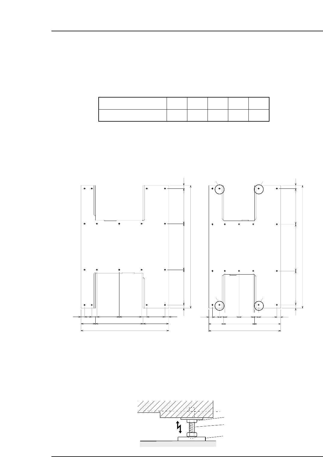
Set leveling sheets in the positions shown below, and adjust the machine until it is level.
Ensure leveling sheets which conform to the board conveyance height are used.
Note: If the height of panel conveyance on the NP-134ME is 930 mm or more he height and
shape of the four leveling sheets circled in the figure below will differ from the other 14
locations. The heights at this time are shown in parentheses in the table above.
Procedure
1. Position the leveling sheets according to the positions indicated below.
2. Position a pair of spirit levels in the base of the machine.
(Vertical and horizontal directions)
3. Adjust the height of each leveling bolt so that the machine is level and the
conveyance height is correct.
4. When you are satisfied that the machine is level, tighten the lock nuts to secure the
leveling position.
NP1MS050
Lock nut
Leveling bolt
Leveling sheet
265
2320
6066587066560
1340
277 576 487
6934126513169
1660
900 485275
3469742342397136
69
69
2320
66587066560 60
100 100
<NP-134E> <NP-134ME>
NP1MS058a
Side 2 Side 2
Side 1
(mm)
Side 1
∗
∗
∗
∗
*
:This symbol is used to indicate leveling sheets that are smaller and shorter then those used at other locations.
Table01a
Board cpmveyance height
Leveling sheet height
900
16
units : mm
910
30
930
40(45)
950
60(60)
965
75(80)
Part 4 Chapter 1 Leveling the Machine
Edition 1.0 4-1-1 NP-134E/134ME Mechanical