np134 mechanical reference-1.1e.pdf.pdf - 第32页
Parts Supply System PFU-4E (for NP-134E) The PFU-4E supplies parts from Power Feeders when it is attached to the machine. Up to 40 Power Feeders 8 mm wide can be loaded on the PFU-4E. The electric and air supplies connec…
3. Functions of Each Part
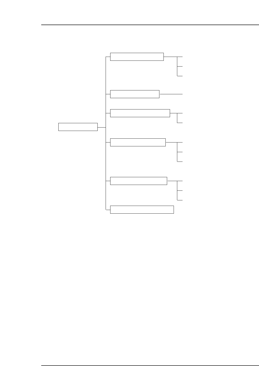
Parts Mounting System
X/Y Robot
There are 2 X/Y robots at the Y-axis; 1 for the placing head, and 1 for the mark camera &
parts camera. The 2 robots work in conjunction, repeatedly picking up and placing parts
with optimum efficiency.
Placing Head
The rotary-type placing head is equipped with 16 nozzles. The positioned nozzle places
parts on the board.
Nozzle Changer
There are 2 nozzle changers where replacement nozzles are stored. Defective nozzles are
automatically replaced, and nozzle assignments are automatically designated when
program changes occur.
Parts mounting system
Parts sypply system
Vision processing system
Board transport system
Electrical control system
Air pressure control system
XY-robot
Placing head
Nozzle station
PFU-4E/5E
Parts camera
In-conveyor
Operation box
Control box
NP-134E/134ME
NP1MN056
Servo box
Main conveyor
Out-conveyor
Mark camera
Part 1 Chapter 3 Functions of Each Part
Edition 1.0 1-3-1 NP-134E/134ME Mechanical

Parts Supply System
PFU-4E (for NP-134E)
The PFU-4E supplies parts from Power Feeders when it is attached to the machine. Up
to 40 Power Feeders 8 mm wide can be loaded on the PFU-4E. The electric and air
supplies connect automatically when the unit is attached to the machine. An automatic
tape cutter can be added as an option.
PFU-5E (for NP-134ME)
The PFU-5E supplies parts from Power Feeders when it is attached to the machine. Up
to 24 Power Feeders 8 mm wide can be loaded on the PFU-5E. The electric and air
supplies connect automatically when the unit is attached to the machine. An automatic
tape cutter can be added as an option.
Vision Processing System
Parts Camera
The parts camera identifies the shape and size of parts picked up by the nozzle. Because
the parts camera is mounted on an X/Y robot, image acquisition is possible both when
the part is picked up, and during motion.
Each placing head has two parts cameras (for wide view and narrow view).
Mark Camera
This is a CCD camera which reads fiducial marks in order to make coordinate corrections
at the board being produced.
Panel Transport System
In-conveyor
The in-conveyor receives panels from the previous machine, and loads them to the main
conveyor. A shuttle moves horizontally along the S1-axis of the in-conveyor, allowing it
to load panels to the dual main conveyor.
Main Conveyor
The main conveyor is a dual conveyor setup, where the panels are clamped during the
placement of parts. When placement is complete, the panels are unloaded to the out-
conveyor.
Out-conveyor
The out-conveyor unloads completed panels to the next machine. A shuttle moves
horizontally along the S2-axis of the out-conveyor, allowing it to unload panels from the
dual main conveyor.
Part 1 Chapter 3 Functions of Each Part
Edition 1.0 1-3-2 NP-134E/134ME Mechanical
Electrical Control System
Operation Box
The operation box is equipped with the buttons (and touch-screen monitor) required to
operate the machine.
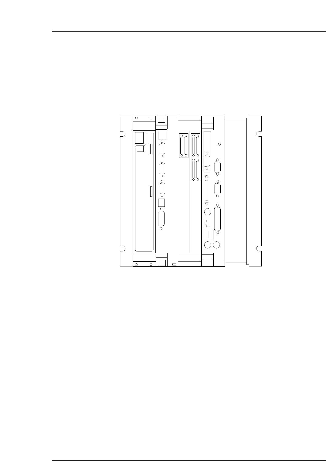
Control Box
The control box contains the electrical circuitry required for machine control.
The control box also contains control boards. Descriptions of each of these boards are
given below.
(a) I/O board
This board transfers signals from sensors and switches to the CPU board, and
controls relays, valves and PFU-4E/5E etc., in accordance with signals from the
CPU board.
(b) Vision Processing Board
This board processes data from the CCD camera which enables parts to be
mounted accurately.
(c) Servo board.
This is a servo motor board. It controls the travel speeds and stop positions for the
following 12 axes:
Y1, X1, I1, Q1, Z1, S1
Y2, X2, I2, Q2, Z2, S2
NP1MN055
(a) (b) (c) (d)
COMA
RESET
COMB
MEZ01 MEZ01
CN1(IN)
CN2(OUT)
Part 1 Chapter 3 Functions of Each Part
Edition 1.0 1-3-3 NP-134E/134ME Mechanical