np134 mechanical reference-1.1e.pdf.pdf - 第74页
2.1 XY -Robot Lubrication (Y -axis LM Guides) Note: The ball screws and LM guides on the X-axis, and the ball screws on the Y-axis are self-lubricating. 1. Arrow marks in the illustrations indicate lubrication points. Bl…
Lubrication Instructions
Illustrations and tables are used to indicate important information about keeping the
machine properly lubricated.
■ Type and Schedule for Lubrication
Within these illustrations, symbols are used to indicate the location, type and schedule
for lubrication.
The following symbols are used.
✔: Apply an appropriate amount of lubricant.
R: Apply for rust prevention.
N/A: Lubrication prohibited.
The lubrication schedules are based on eight hours of operation per day, five days per
week (40 hours) and 20 days per month (160 hours). However, if the machines are being
operated in two or three shifts per day, the lubrication schedules should be used as
follows.
Every day: Eight hours from when the machine is turned on, after every
eight hour shift, or after one day's operation.
Weekly: After 40 hours of operation, whether the machine is being used
in two or three shifts, or after one week's operation.
Monthly: After 160 hours of operation, whether the machine is being
used in two or three shifts, or after one month's operation.
Every 3 months: After 480 hours of operation, whether the machine is being
used in two or three shifts, or after three month's operation.
Every 6 months: After 960 hours of operation, whether the machine is being
used in two or three shifts, or after six month's operation.
■ Locations for Lubrication
Locations for lubrication are indicated in the illustrations using arrows and numbers.
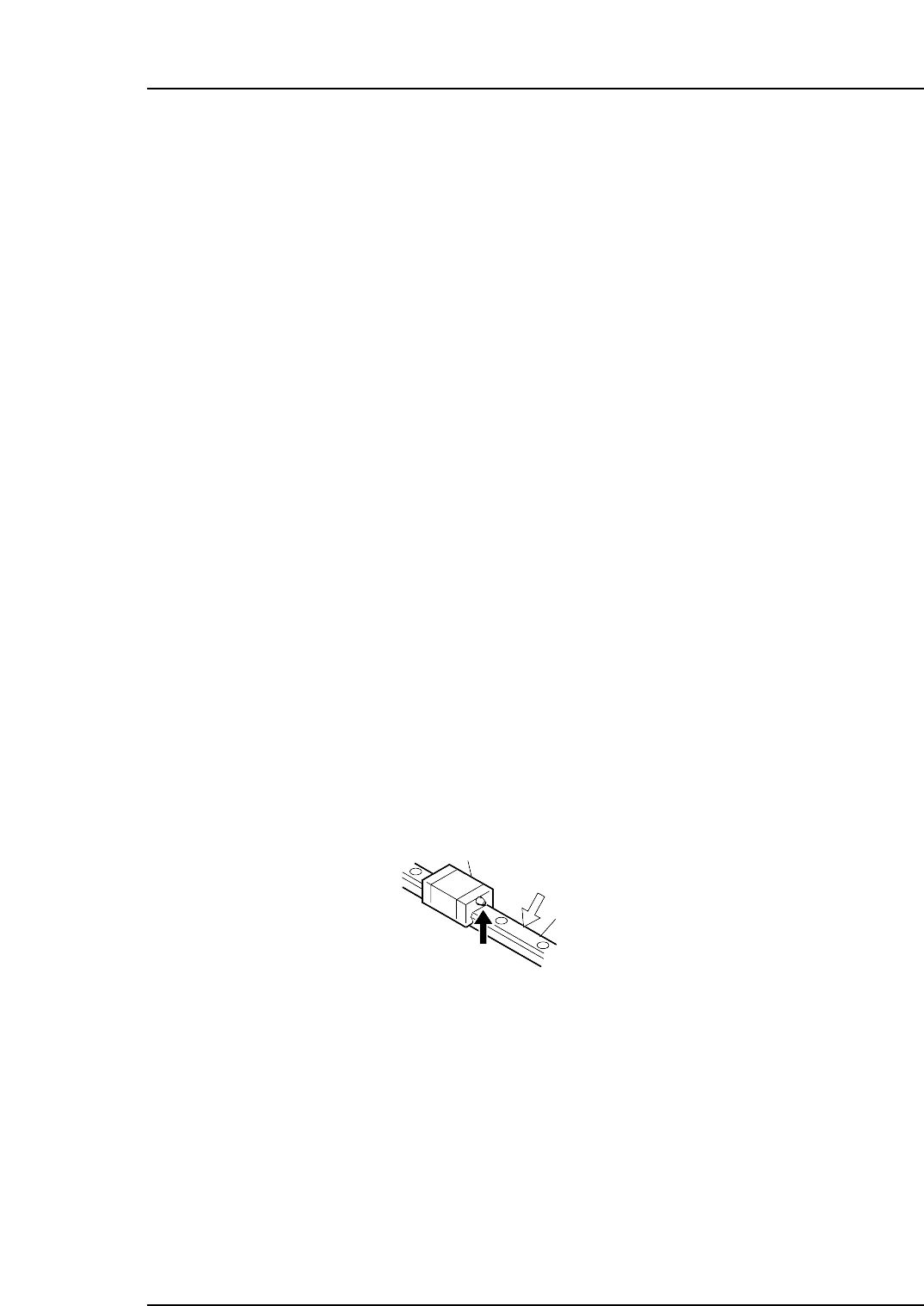
White arrows are used to indicate surfaces that require greasing or oil. Black arrows
indicate grease nipples, and signify that grease should be inserted using a grease pump.
Note: Even LM blocks that do not have a nipple can be lubricated by applying grease between the
block and the LM rail (bearing mechanism). The grease that adheres to the ball bearings
and rollers will be taken into the LM block and thereby serve to lubricate the LM block.
■ Lubrication Checklist
A lubrication checklist is provided at the end of this chapter. This checklist should be
used as follows.
1. Check the lubrication points corresponding to the reference numbers shown in the
illustrations.
2. Mark each check box after lubricating each point.
LM block
(1)
(2)
LM001
LM rail
Part 3 Chapter 2 Lubrication
Edition 1.1 3-2-3 NP-134E/134ME Mechanical
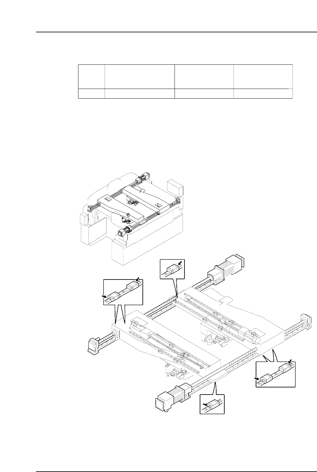
2.1 XY-Robot Lubrication (Y-axis LM Guides)
Note: The ball screws and LM guides on the X-axis, and the ball screws on the Y-axis are
self-lubricating.
1. Arrow marks in the illustrations indicate lubrication points.
Black arrows indicate points where a grease gun is required.
2. Numbers shown in parentheses correspond to items on the checklist provided at
the end of this chapter.
NP1ML058
(2)
(1)
(1)
(3)
(4)
(4)
Lubrication
Points
No.
Lubrication
Schedule
Daphne Eponex
No. 2
LM block
1 ~ 4
✔ Monthly
Table-001a
✔ : Lubricate N/A : Do not lubricate
Part 3 Chapter 2 Lubrication
Edition 1.1 3-2-4 NP-134E/134ME Mechanical
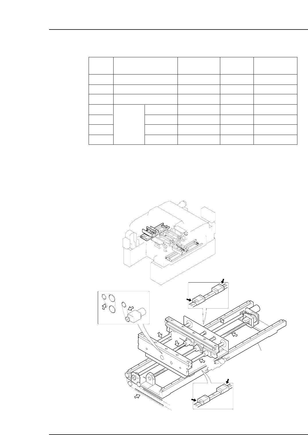
2.2 In-conveyor Lubrication
1. Arrow marks in the illustrations indicate lubrication points.
Black arrows indicate points where a grease gun is required.
2. Numbers shown in parentheses correspond to items on the checklist provided at
the end of this chapter.
NP1ML059
(9)
(6)
(11)
(11)
(12)
(10)
(10)
Shuttle
(5)
(7)
(8)
(8)
(13)
Lubrication
Points
Lubrication
Schedule
Daphne Eponex
No. 2
Ball screw
Shuttle
✔
Biral T&D
N/A
Every year
Table-002-1a
✔ : Lubricate N/A : Do not lubricate
No.
5
Shafts
✔ N/A
Every year
6, 7
Chain
N/A ✔
Every 6 months
8
Ball screw
✔ N/A
Monthly
9
LM block
✔ N/A
Monthly
10, 11
Shaft
✔ N/A
Monthly
12
Chain
N/A ✔
Every 6 months
13
Part 3 Chapter 2 Lubrication
Edition 1.1 3-2-5 NP-134E/134ME Mechanical