np134 mechanical reference-1.1e.pdf.pdf - 第91页
3.5 Parts Camera UV Lamp Replacement Point The UV lamp will grow dim over time, and should be replaced periodically (after 2000 hours of machine operation). The jig (DFPJ0060) is necessary to measure the UV-lamp bracket …
For Main Conveyor
WARNING
Always be sure to cut the main power before carrying out
any work.
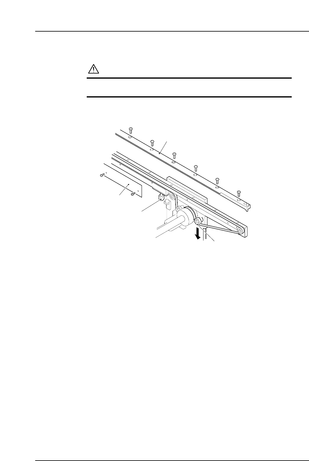
1. Loosen the tension pulley mounting bolt, and then loosen the belt tension.
2. Remove plates A and B.
3. Replace the conveyor belt with a new one.
4. Secure the tension pulley where it is attached with 15 N (1.5 kgf) applied in the
direction shown by the arrow. Tighten the tension pulley with a torque of 4 N·m
(40 kgf·cm).
5. Reattach the plates A and B.
Note: Adjust the lifter plate bolt after plate B has been attached.
NP1MR054
Plate A
Plate B
Lifter plate bolt
Tension pully
Part 3 Chapter 3 Replacing Consumable Parts
Edition 1.0 3-3-6 NP-134E/134ME Mechanical
3.5 Parts Camera UV Lamp Replacement
Point
The UV lamp will grow dim over time, and should be replaced periodically (after 2000
hours of machine operation). The jig (DFPJ0060) is necessary to measure the UV-lamp
bracket height.
Procedure
Caution
Ensure the nozzle station is lowered before carrying out
inching. The XY-robot will be damaged if it interferes with
the nozzle station.
WARNING
Always be sure to cut the main power before carrying out
any work.
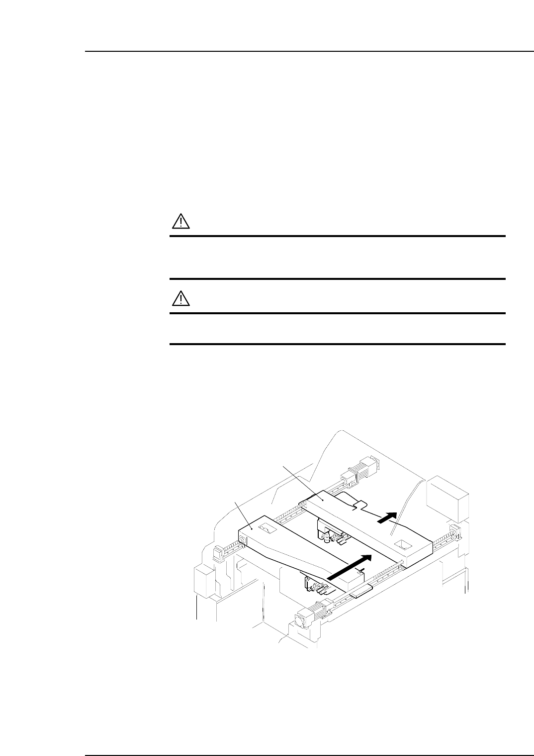
1. Use the inching operation to move XY robots 1 and 2 to “side 2” of the machine.
Note: The procedure for replacing the UV lamp at XY robot 1 is explained here. When
replacing the UV lamp at XY robot 2, move XY robots 1 and 2 to “side 1” of the
machine.
(Side 1)
(Side 2)
XY-robot 1
XY-robot 2
NP1ML053
Part 3 Chapter 3 Replacing Consumable Parts
Edition 1.0 3-3-7 NP-134E/134ME Mechanical
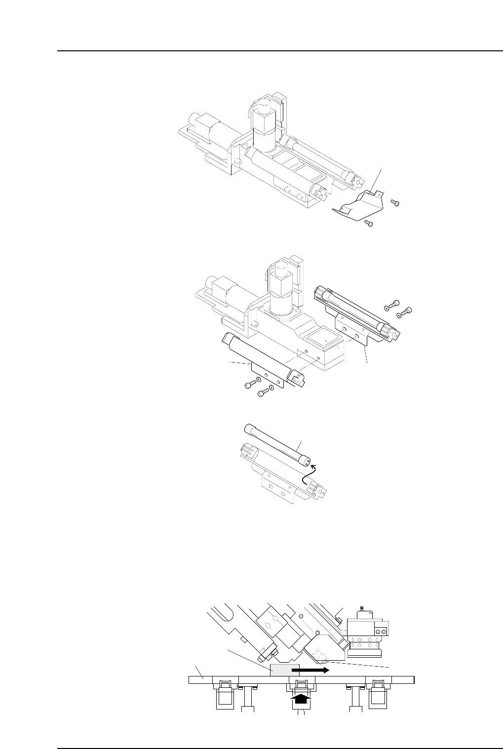
2. Detach the cover from the end of the camera unit.
3. Remove the UV lamp holder together with its bracket.
4. Extract the UV lamp from the UV lamp holder, and install a new UV lamp.
Note: Handle the UV lamp with care. The glass portion of the lamp may break if excessive
force is applied.
5. Reattach the UV-lamp holder bracket and cover after replacing the lamp. Next,
remove the nozzle station shutter plate, and place the jig (DFPJ0060) on the top of
the nozzle station which is at the uppermost position. Slide the jig back and forth
ensuring there is no interference with the UV-lamp bracket.
Nozzle station
Jig (DFPJ0060)
UV-lamp bracket
NP1MR067a
NPMR065
UV lamp
NPMR064
Bracket
Bracket
NPMR063
Cover
Part 3 Chapter 3 Replacing Consumable Parts
Edition 1.0 3-3-8 NP-134E/134ME Mechanical