np134 mechanical reference-1.1e.pdf.pdf - 第93页
3.6 Replacing the Filter Regulator Point The air flowing through the pneumatics of the machine must be clean. Replace the regulator filter if it becomes too dirty. Procedure W ARNING Always be sure to cut the main power …
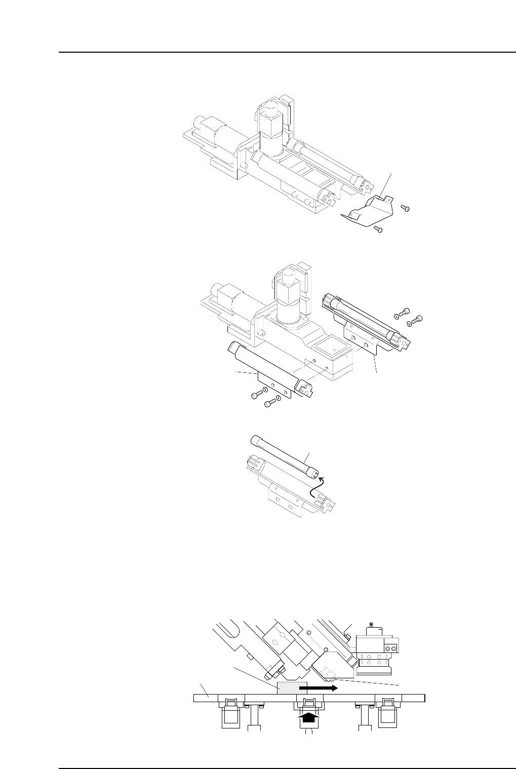
2. Detach the cover from the end of the camera unit.
3. Remove the UV lamp holder together with its bracket.
4. Extract the UV lamp from the UV lamp holder, and install a new UV lamp.
Note: Handle the UV lamp with care. The glass portion of the lamp may break if excessive
force is applied.
5. Reattach the UV-lamp holder bracket and cover after replacing the lamp. Next,
remove the nozzle station shutter plate, and place the jig (DFPJ0060) on the top of
the nozzle station which is at the uppermost position. Slide the jig back and forth
ensuring there is no interference with the UV-lamp bracket.
Nozzle station
Jig (DFPJ0060)
UV-lamp bracket
NP1MR067a
NPMR065
UV lamp
NPMR064
Bracket
Bracket
NPMR063
Cover
Part 3 Chapter 3 Replacing Consumable Parts
Edition 1.0 3-3-8 NP-134E/134ME Mechanical
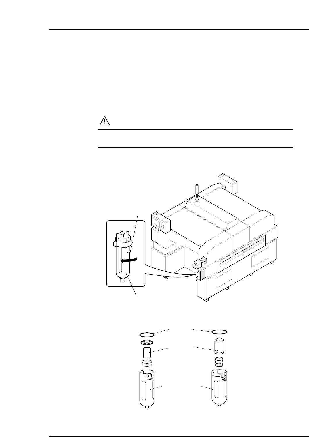
3.6 Replacing the Filter Regulator
Point
The air flowing through the pneumatics of the machine must be clean. Replace the
regulator filter if it becomes too dirty.
Procedure
WARNING
Always be sure to cut the main power before carrying out
any work.
Remove the filter regulator cover and discharge the air from the lines.
1. Remove the filter case by turning it while pressing the lock knob down.
2. Replace the filter regulator with new ones.
NP1ML056-1
O-ring
Filter
Filter case
NP1ML056
Filter case
Lock knob
Part 3 Chapter 3 Replacing Consumable Parts
Edition 1.0 3-3-9 NP-134E/134ME Mechanical
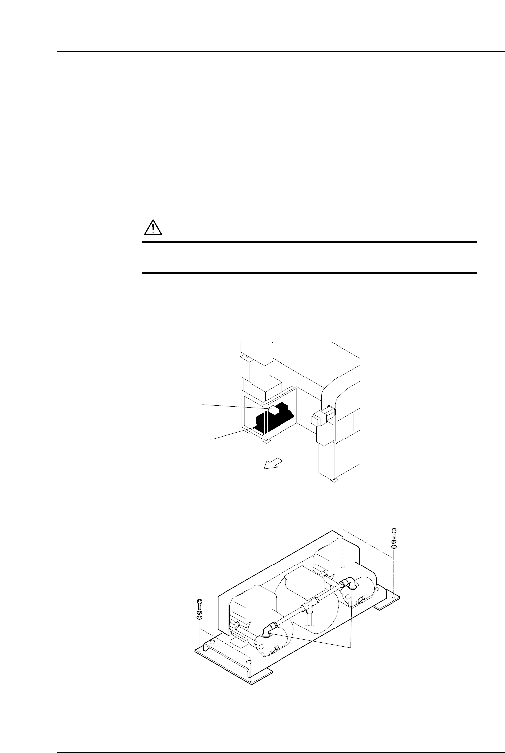
3.7 Replacing the Vacuum Pump
(Every 10000 Hours)
Point
Replace the vacuum pump after 10000 hours of operating the machine, or if the vacuum
pressure falls below -90 kPa.
Procedure
WARNING
Always be sure to cut the main power before carrying out
any work.
1. Remove the door and cover from the vacuum pump box.
2. Remove the wiring (red, white, black, and ground) from the terminal block on the
top of the pump.
3. Remove the four bolts securing the vacuum pump assembly, and detach the
assembly from the machine.
4. Remove the two elbow joints shown above from the piping.
NP1ML076
Elbow joints
Side 2
NP1ML075a
Vacuum pump
Terminal block
Part 3 Chapter 3 Replacing Consumable Parts
Edition 1.0 3-3-10 NP-134E/134ME Mechanical