np134 mechanical reference-1.1e.pdf.pdf - 第98页
Notes: Part 3 Chapter 3 Replacing Consumable Parts Edition 1.0 3-3-14 NP-134E/134ME Mechanical

3. Insert the tip of the pin into the hole in the board and then secure the unit in
position.
Photolink board
Tip of pin
NP1MR070
Part 3 Chapter 3 Replacing Consumable Parts
Edition 1.0 3-3-13 NP-134E/134ME Mechanical

Notes:
Part 3 Chapter 3 Replacing Consumable Parts
Edition 1.0 3-3-14 NP-134E/134ME Mechanical
4. Adjustment
4.1 Adjusting the Conveyor Sensor Delay Times
Point
When conveying boards which have slits (such as multi-blok boards, etc.), the sensor
may mistake the slit for the edge of the board. To prevent this, the sensor delay time
should be adjusted. There are two sensor types: type “A” and type “B”.
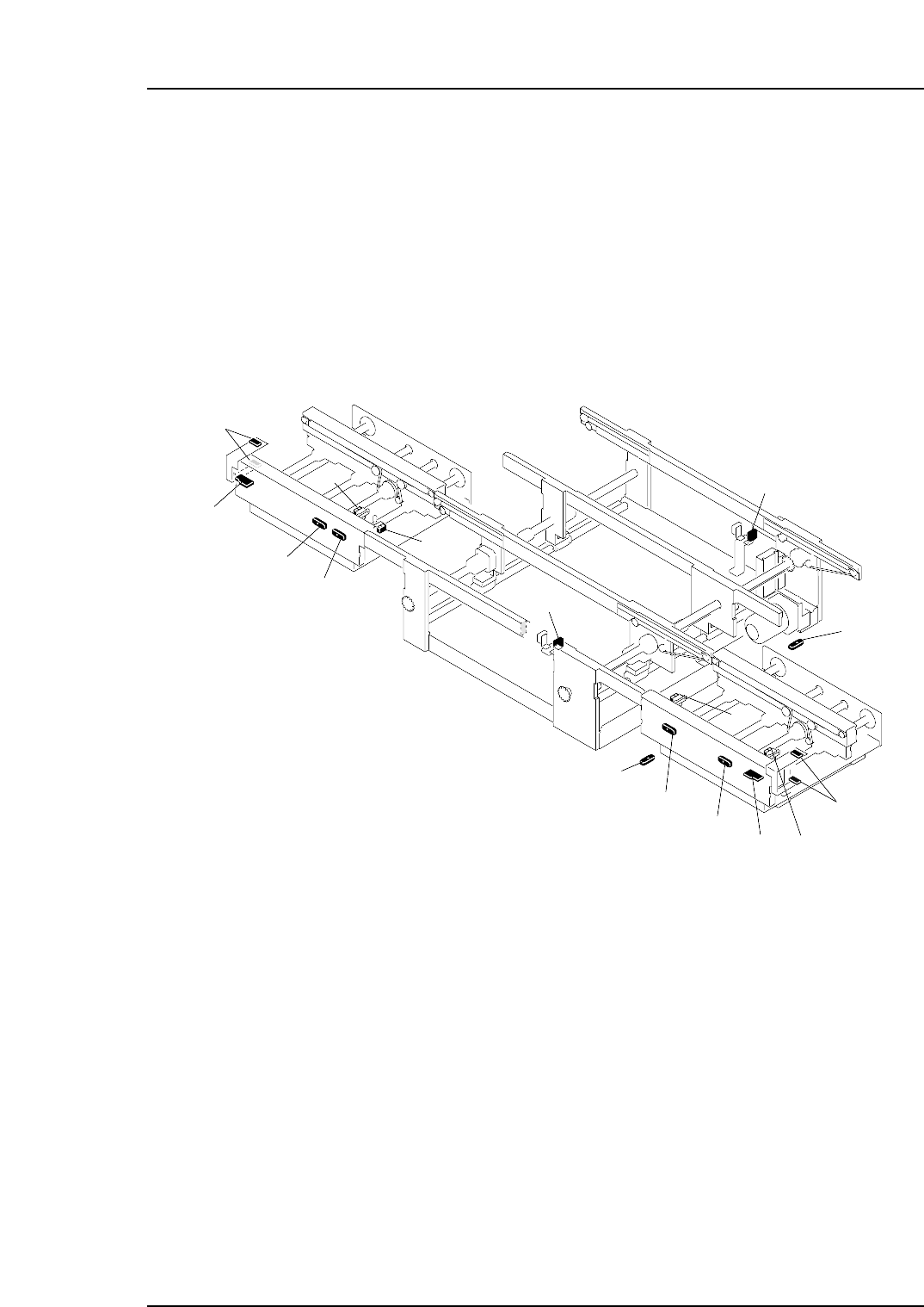
The sensor and amplifier unit configuration is shown below.
NP1MT002a
10
1
2
4
6
3
5
13
8
14
12
15
16
7
11
9
1. In-conveyor panel loading sensor
2. Amplifier unit (type "B") for in-conveyor panel loading sensor
3. In-conveyor panel arrival sensor
13. Out-conveyor panel arrival sensor
7. Main conveyor-1 panel arrival sensor
8. Timer unit (type "A") for main conveyor-1 panel arrival sensor
9. Main conveyor-2 panel arrival sensor
5. In-conveyor panel unloding sensor
6. Timer unit (type "A") for in-conveyor panel unloading sensor
10. Timer unit (type "A") for main conveyor-2 panel arrival sensor
4. Timer unit (type "A") for in-conveyor panel arrival sensor
14. Amplifier unit (type "A") for out-conveyor panel arrival sensor
15. Out-conveyor panel unloading sensor
11. Out-conveyor panel unloding sensor
12. Timer unit (type "A") for out-conveyor panel unloading sensor
16. Amplifier unit (type "B") for out-conveyor panel unloading sensor
Part 3 Chapter 4 Adjustment
Edition 1.0 3-4-1 NP-134E/134ME Mechanical