SiplaceX4_en.pdf - 第107页
1 - 7 S tudent Guide SIPLACE X Edition 09/2005 3 Communication and Control 7 3.4.1.2 Zero pulse at the position encoder Each incrementa l encoder system needs initializing. This mea n a reference run is executed for each…
1 - 6
Student Guide SIPLACE X
3 Communication and Control Edition 09/2005
6
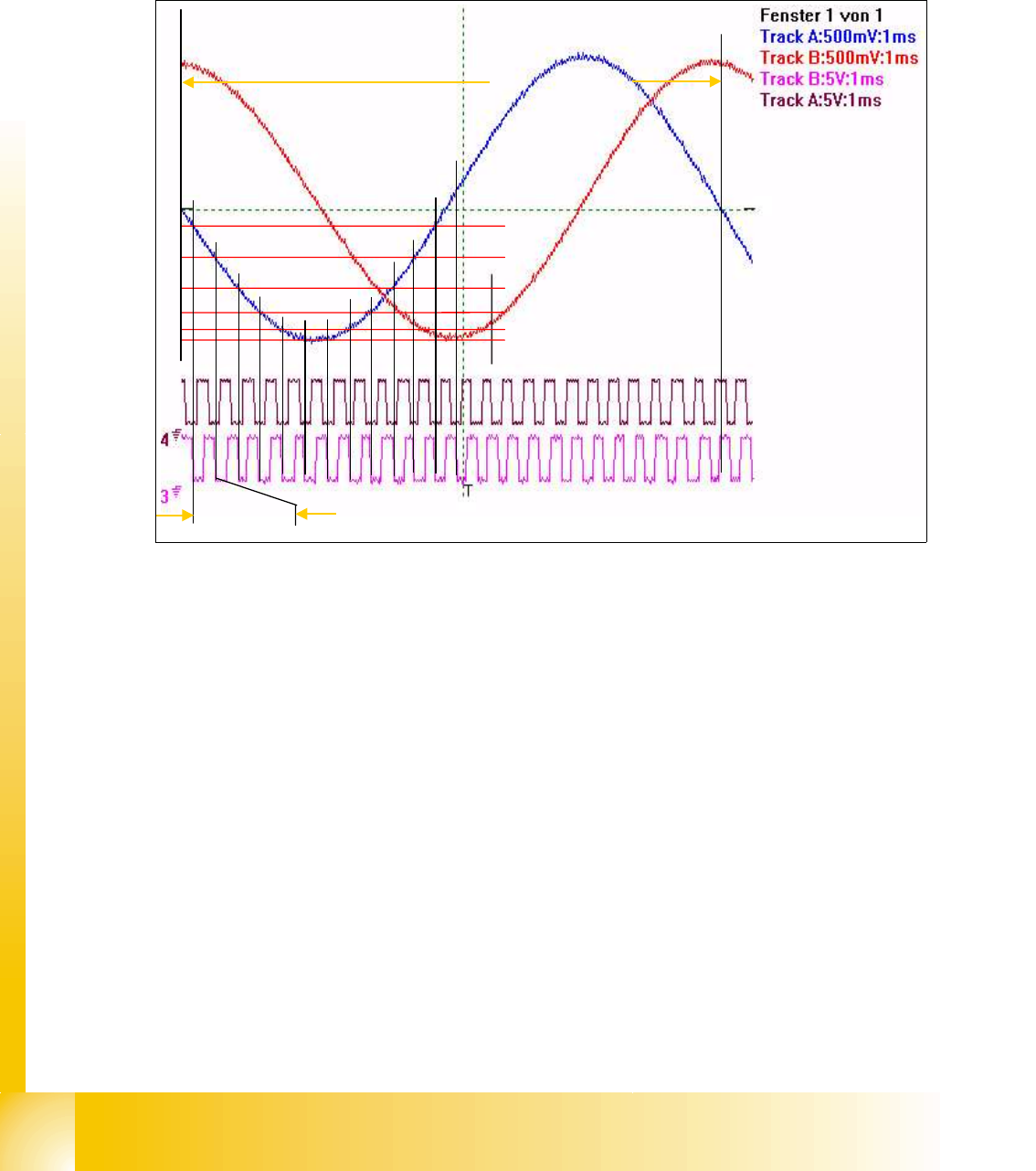
The position is determined by a position counter on the axis controller. The moving direction of the
axis is determined by the phase shift of the Tracksignals (a leading Track A signal means moving
to the right; a leading Track B signal means moving to the left).
To make the encoder system robust for the high resolution we multiply the frequency of the ana-
loge signal and create a high resolution digital measuring system.
Fig. 3.4 - 2 Principle signal multiplication at analog Track signals of a gantry axis
Legend
In principle the track signal is multiplied by a ’Schmitt Trigger’ circuit. By comparing analoge and
digital signals on our axes you will find a multiplication by 25 (see Fig. 3.4 - 2), 10 or by 1.
The track signals of the C&P head axes can only be measured as digital signals i.e. the transfor-
mation of the analogue track signals into digital track signals occurs directly in the incremental en-
coder without any Test connector in that encoder case.
(1) Analoge track A signal Incremental
encoder
(2) Analoge track B signal Incremental
encoder
(3) Digital track A signal at Test connector (4) Digital track B signal at Test connector
(5) Period time of analoge track signal (6) Period time of digital track signal
1
2
5
6
1 - 7
Student Guide SIPLACE X
Edition 09/2005 3 Communication and Control
7
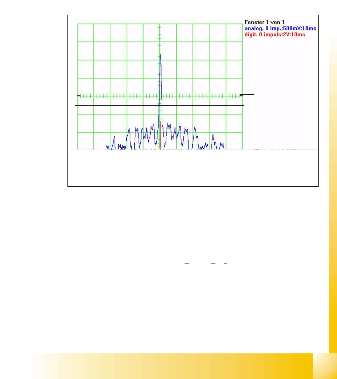
3.4.1.2 Zero pulse at the position encoder
Each incremental encoder system needs initializing. This mean a reference run is executed for
each axis.
At the reference run the system searches for a certain position - the signal for this is the Zero
pulse. The Zero pulse is an analoge signal and a ’Schmitt Trigger’ circuit digitizes it.
(calibrate ’Zero line’ to the middle of the screen before this measurement).
Fig. 3.4 - 3 Analoge and digital zero pulse signals (’zero line’ adjusted to middle)
At about 2.5 V threshold the ’Schmitt Trigger’ circuit creates a short high peak, the Zero pulse for
the position control system. If the encoder is mounted to close to the scale one of the noise glit-
ches could override the ’Schmitt Trigger’threshold. This means the Zero pulse is detected at a
wrong position of the Gantry axis, so it could lead to a board offset. (At X3 or X4 machines this
could lead to a placement offset .) The digital Zero pulse is measured with a probe at Pin 8 of the
test connector.
The Zero pulse output of the Axistestbox (or S
IPLACE Axis Tester SAT ) is where the inverted
Zero pulse can be measured.
3
The analoge Zero pulse
has to be 0.3 V higher
than the Trigger threshold
for the digital pulse
Schmitt Trigger Threshold
Glitches (signal noise)
should not override the limit
0.3 V less than Trigger
threshold!
1 - 8
Student Guide SIPLACE X
3 Communication and Control Edition 09/2005
8
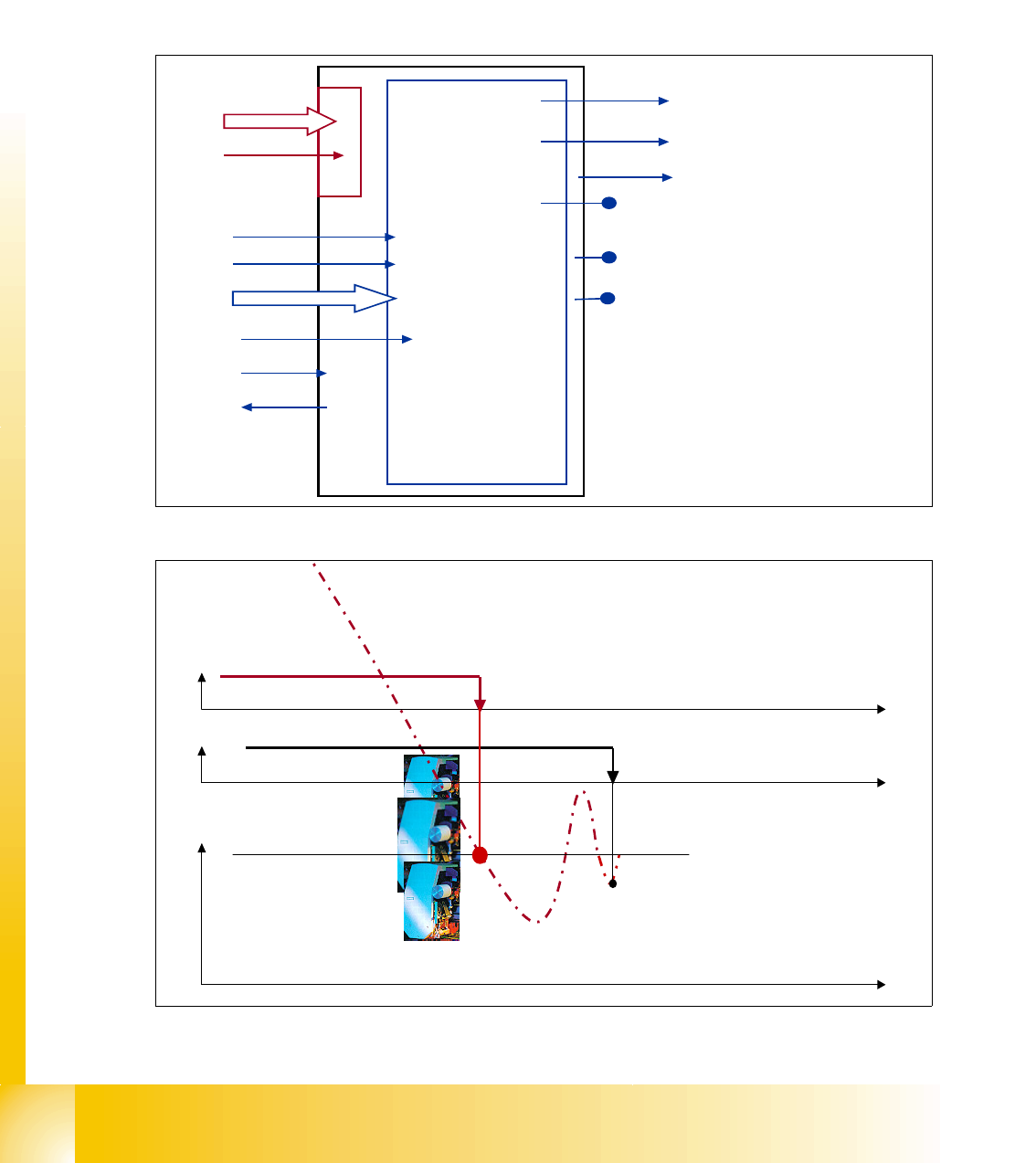
3.4.2 Axis dynamic basics
Each axis starts from a position with acceleration a constant speed phase and deceleration should
move the axis into a target position. The dynamic movement is completely digital controlled at the
Siplace X machines. A powerful digital processor permanently adjusts the axis behavior to each
state of axis dynamic. This mean all adjustments like speed (Tacho) and positioning quality (P-
gain) at servo amplifier are removed. The control signals are different for this new axis control prin-
ciple.
Fig. 3.4 - 4 Digital controlled axis at Siplace X
Fig. 3.4 - 5 Positioning with overshoot into target position
I for Light barrier bottom
Servo Ready
position data
start
Track signals
Force value
Control signal 1 Servo
Control signal 2 Servo
Servo ON
Current measuring point
uncommutated current signal (V
reg
)
output V
nominal
output force
End signal
Axis
controller
at main
board
VC 3 controller
Act. pos. equal
nomial pos.
-
signal
target position
t
END-signal
Axis mechanic
within tolerable
position deviation
Position counter
count into target.
Overshoot 1 ‘15’
Overshoot 2 ‘-8’
Overshoot 2 ‘3’
t
t