SiplaceX4_en.pdf - 第122页
1 - 52 S tudent Guide SIPLACE X 3 Communication and Control Edition 09/2005 52 3.5.2 Function Control and T r oubleshooting for Service Work This section provides an overview o f how to assign the one wire bus subsystems…
1 - 51
Student Guide SIPLACE X
Edition 09/2005 3 Communication and Control
51
Fig. 3.5 - 9 NC control board only at the 20 C&P head nozzle changer
Fig. 3.5 - 10
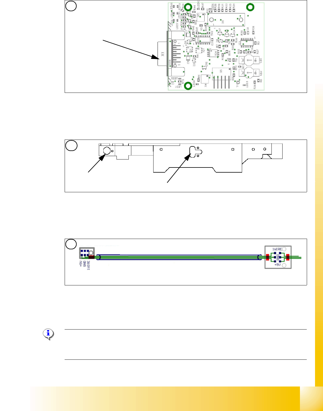
Position of temperature sensors on the head plate
Fig. 3.5 - 11 Temperature sensors / gantry recognition
Hinweis:
The temperatursensor are connected directly on the connector X20 or X21 on the Head interface
C500. You can use one of the two connectors. 3
Display (2 LED‘s) for NC C&P20 (The LED‘s are invisible because there is a cover under the NC)
Light barrier NC open/closed and Valve NC open/closed
5. Temperature sensor on the PCB cam-
era
(6) Temperature sensor/ EEPROM gantry recog-
nition
7. Temperature sensor on the PCB cam-
era
(8) Temperature sensor/ EEPROM gantry recog-
nition
5
Connection to 1 wire
hub for NC
1
2
6
6
21
1 - 52
Student Guide SIPLACE X
3 Communication and Control Edition 09/2005
52
3.5.2 Function Control and Troubleshooting for Service Work
This section provides an overview of how to assign the one wire bus subsystems to the relevant
hardware assemblies, enabling a structured approach to service work.
3.5.2.1 Subsystem Query in PA1
– Connect the service laptop to the machine CAN bus at PA1.
Make sure that the cable is connected to channel 1 for PA1 and that, at least the transmitter is
connected to channel 2 of the Kvaser card.
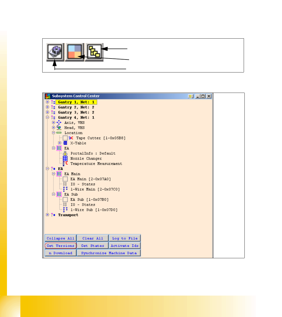
– Start the "CACCIA" software and check the machine configuration with Caccia.
– Doubleclick to open the subsystem control center.
Fig. 3.5 - 12 Icons: properties, machine configuration, subsystem control center
Fig. 3.5 - 13 Subsystem control
–Click on the "Get Versions" button.
The system will display all available subsystems with their firmware versions and CAN IDs.
Subsystem control center
Machine configuration window
Properties (settings, restart Kvaser card)
1 - 53
Student Guide SIPLACE X
Edition 09/2005 3 Communication and Control
53
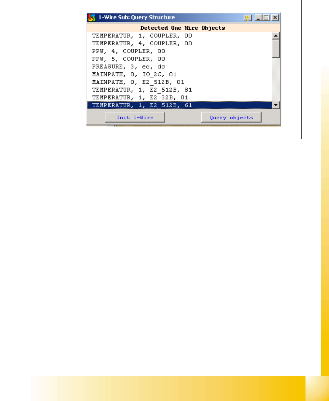
– Doubleclick on the IO SUB (PA1) directory to open the 1 wire subdirectory. The following dialog
will appear:
Fig. 3.5 - 14 1 wire sub query structure
Click on the "Query objects" button to display all PA1 subsystems.
The function "Init 1wire" is not required, as the one wire bus system is initialized when the machine
is switched on. (If initialization is necessary, you may need to click on the button 2 or 3 times.)