SiplaceX4_en.pdf - 第124页
1 - 54 S tudent Guide SIPLACE X 3 Communication and Control Edition 09/2005 54 Allocation of subsystems to the hardware components Example of P A 1 on HF/HF3 PPW --> Nozzle Changer (NC) Subsystem Hardware component s …
1 - 53
Student Guide SIPLACE X
Edition 09/2005 3 Communication and Control
53
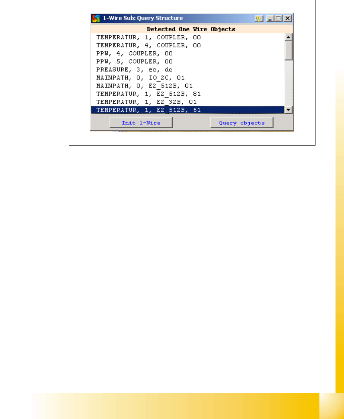
– Doubleclick on the IO SUB (PA1) directory to open the 1 wire subdirectory. The following dialog
will appear:
Fig. 3.5 - 14 1 wire sub query structure
Click on the "Query objects" button to display all PA1 subsystems.
The function "Init 1wire" is not required, as the one wire bus system is initialized when the machine
is switched on. (If initialization is necessary, you may need to click on the button 2 or 3 times.)

1 - 54
Student Guide SIPLACE X
3 Communication and Control Edition 09/2005
54
Allocation of subsystems to the hardware components
Example of PA1 on HF/HF3
PPW --> Nozzle Changer (NC)
Subsystem Hardware components Comments
Temperature, 1, coupler, 00 PCB:1 wire trailing interface Trailing interface gantry 1
Temperature, 4, coupler, 00
CB:1 wire trailing interface
Trailing interface gantry 4
PPW, 4, coupler, 00 1 wire hub for NC Hub for NC at location 4 for NC row 1/2
PPW, 1, coupler, 00 1 wire hub for NC Hub for NC at location 1 for NC row 1/2
Mainpath, 0, IO_2C, 01
Mainpath, 0, E2_512B, 01
1 wire RS232 bridge I/O module board (to be later integrated
into I/O module)
Temperature, 1, E2_512B, 81
Temperature, 1, E2_32B, 01
Temperature, 1, E2_512B, 61
Temperature, 1, temperature, 10
Temperature, 1, temperature, 11
Temperature, 1, IO_2C,01
Temperature sensors
gantry 1
The two temperature sensors form a unit
and can only be replaced as a set. The
part for the gantry recognition can not
change.
Temperature, 4, E2_512B, 81
Temperature, 4, E2_32B, 01
Temperature, 4, E2_512B, 61
Temperature, 4, temperature, 10
Temperature, 4, temperature, 11
Temperature, 4, IO_2C,01
Temperature sensors
gantry 4
The two temperature sensors form a unit
and can only be replaced as a set. The
part for the gantry recognition can not
change.
PPW, 4, E2 32B, 81
PPW, 4, AD, 03
PPW, 4, AD, 15
PPW, 4, AD, 16
1 wire hub for NC at location
4
Shows that the 1 wire hub is connected.
PPW, 4, E2_32, 01
PPW, 4, AD, 01
PPW, 4, IO_8C, 01
Control board in NC
gantry 4, in C&P20 NC only
Control board of NC row 1.
PPW, 4, E2_32, 02
PPW, 4, AD, 02
PPW, 4, IO_8C, 02
Control board in NC
gantry 4, in C&P20 NC only
Control board of NC row 2.
PPW, 1, E2_32B, 81
PPW, 1, AD, 03
PPW, 1, AD, 15
PPW, 1, AD, 16
1 wire hub for NC at location1 Shows that the 1 wire hub is connected.
PPW, 1, E2_32B, 01
PPW, 1, AD, 01
PPW, 1, IO_8C, 01
Control board in NC
gantry 1, in C&P20 NC only
Control board of NC row 1.
PPW, 1, E2_32B, 02
PPW, 1, AD, 02
PPW, 1, IO_8C, 02
Control board in NC
gantry 1, in C&P20 NC only
Control board of NC row 2.
1 - 55
Student Guide SIPLACE X
Edition 09/2005 3 Communication and Control
55
3.5.2.2 Function Control with Caccia
Nozzle changer used as example:
In addition to the SITEST program, there are two other options for testing the function of the nozzle
changer.
1. NC menu 3
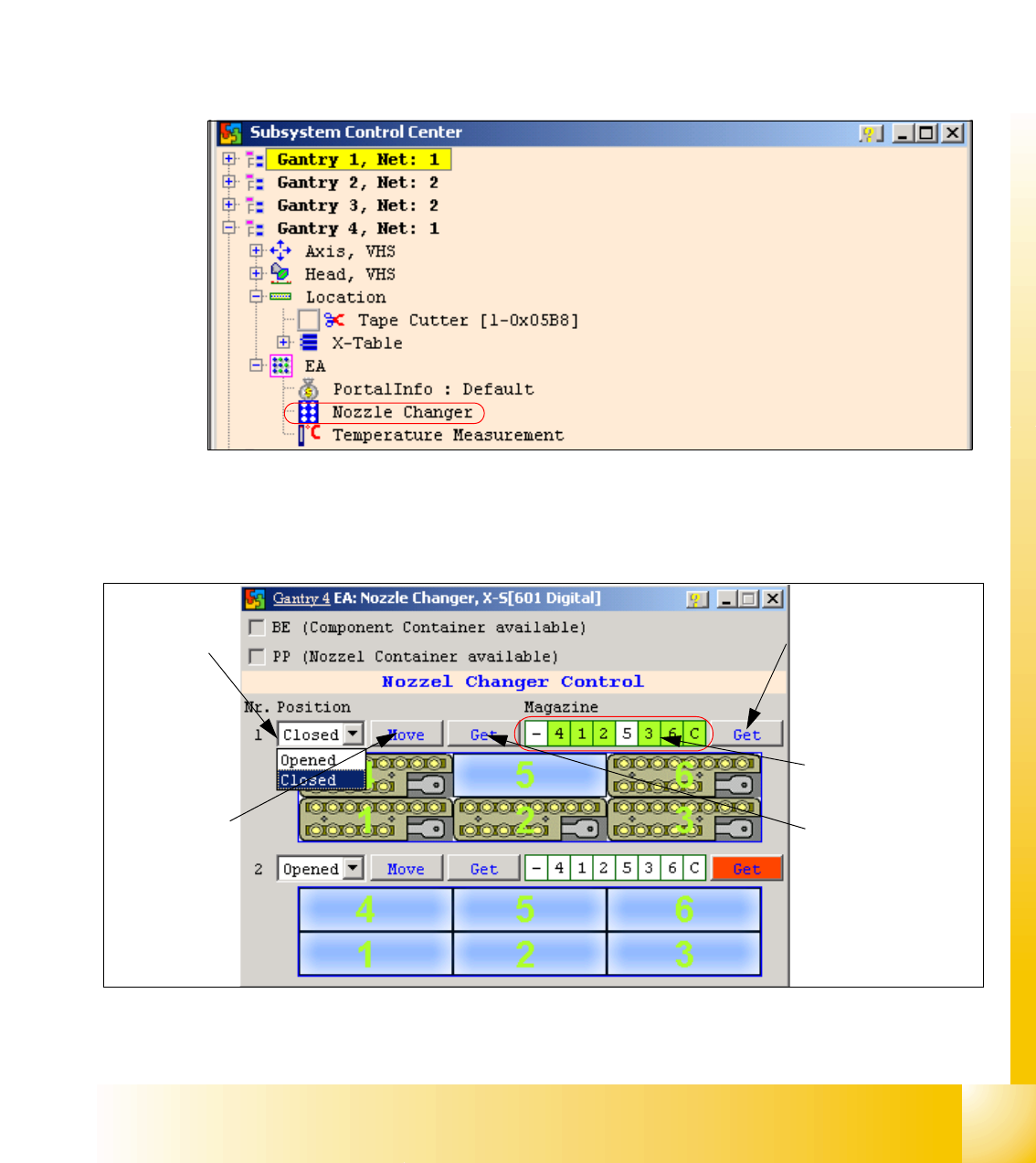
– Open the IO directory of the relevant location in the subsystem control center.
– Doubleclick on Nozzle Changer.
Fig. 3.5 - 15 Subsystem control center (nozzle changer)
– the following menu will appear:
Fig. 3.5 - 16 I/O nozzle changer
Status query maga-
zine (micro switch un-
der the magazine)
Selection win-
dow, open/
close NC row
1
Status display
magazine
Performs the
selected func-
tion
Status display
NC opened / closed