SiplaceX4_en.pdf - 第130页
1 - 60 S tudent Guide SIPLACE X 3 Communication and Control Edition 09/2005 60 3.5.3.2 Overview Initialization of the One W ire Bus (1) CAN BUS command for initialization (2) CAN BUS command sent. (3) Subsystems give a m…
1 - 59
Student Guide SIPLACE X
Edition 09/2005 3 Communication and Control
59
3.5.3 One wire Bus Siplace X machine
The structure of the One Wire Bus Siplace X was changed in opposite the HF/HF3 machine.
With the new hardware structur of the bus system the allocation of subsystems to the hardware
components is different (see table).
Attention: New Application on the I/O moduls necessary! (BIOS E0100323, Application E0110350
or higher)
During the initialization procedure all subsystems send a message via the public byte by yourself.
The public byte comes from each subsystem of the machine via the CAN ID +3hex. If the state of
a subsystem changes, the subsystem reports automatically and without request of the application.
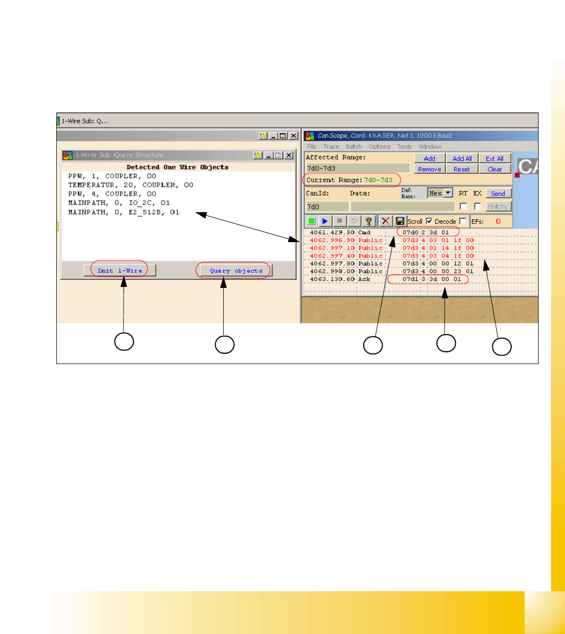
3.5.3.1 Communication One Wire
Fig. 3.5 - 18 Communication with the one wire Interface RS232 on the I/O module
(1) "Init 1 Wire" send the command via the CAN ID 7d0 for PA1.
(2) Query objects shows the decoded Public Bytes.
(3) Net window: 07d0 3d 01 command Initialization of the One Wire Bus.
(4) 5 Public bytes from the Subsystem RS232 Interface on the I/O module
1. 03 01 1f 00 --> 03 Subsystem NC / 01 Gantry / 1f Coupler
2. 01 14 1f 00 --> 01 Subsystem Temperature Gantry(1/4) / 14 1k EEPROM / 1f Coupler
3. 03 04 1f 00 --> 03 Subsystem NC / 04 Gantry / 1f Coupler
4. 00 00 12 01 --> 12 I/O component and EEPROM
5. 00 00 23 01 --> 23 4k EEPROM
(5) Acknowledge (Answer) Command CAN ID +1hex --> 3d 00 01
1
2
4
3
5
1 - 60
Student Guide SIPLACE X
3 Communication and Control Edition 09/2005
60
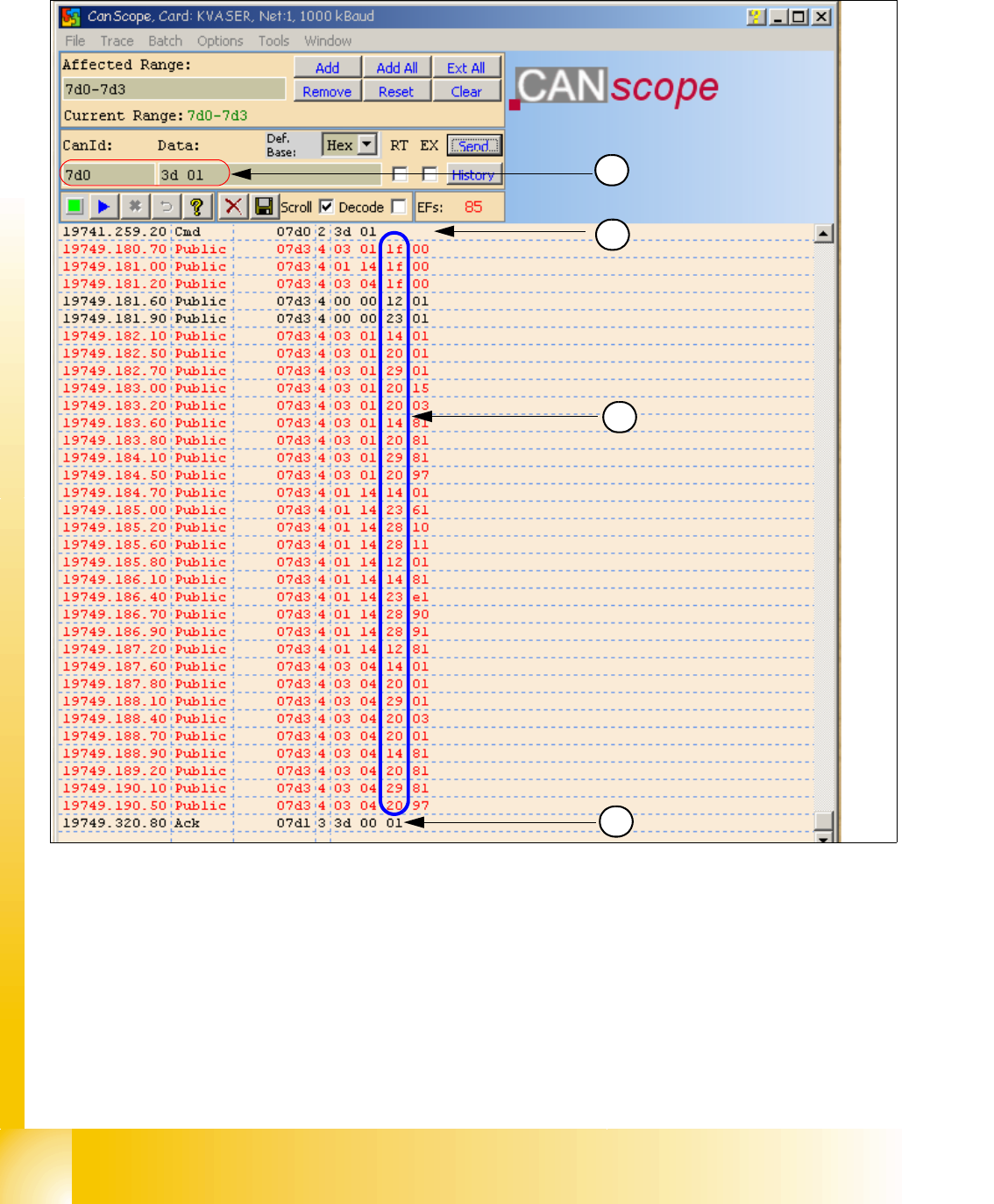
3.5.3.2 Overview Initialization of the One Wire Bus
(1) CAN BUS command for initialization
(2) CAN BUS command sent.
(3) Subsystems give a message via the public bytes
1f --> Coupler 12 --> I/O component with EEPROM 14 --> 1k EEPROM
20 --> 4 channel A/D 23 --> 4k EEPROM 28 --> Temperature
29 --> 8 x I/O component
(4) Answer initialization successful.
1
2
4
3

1 - 61
Student Guide SIPLACE X
Edition 09/2005 3 Communication and Control
61
Allocation of subsystems to the hardware components
e.g. Siplace X PA1
PPW --> Nozzle changer (NC)
Subsystem Hardware components Notes
PPW, 1, Coupler, 00 RS232 Interface on the I/O
module
Temperatur, 20, Coupler, 00
RS232 Interface on the I/O
module
PPW, 4, Coupler, 00 RS232 Interface on the I/O
module
Mainpath, 0, IO_2C, 01
Mainpath, 0, E2_512B, 01
RS232 Interface on the I/O
module
RS232 Interface board will be integrated
in the I/O module later.
Temperatur, 20, E2_32B, 01
Temperatur, 20, E2_512B, 61
Temperatur, 20, Temperatur, 10
Temperatur, 20, Temperatur, 11
Temperatur, 1, IO_2C,01
Temperature sensors
Gantry 1
The two temperature sensors form a unit
and can only be replaced as a set. The
part for the gantry recognition can not
change.
Temperatur, 20, E2_32B, 81
Temperatur, 20, E2_512B, e1
Temperatur, 20, Temperatur, 90
Temperatur, 20, Temperatur, 91
Temperatur, 20, IO_2C,81
Temperature sensors
Gantry 4
The two temperature sensors form a unit
and can only be replaced as a set. The
part for the gantry recognition can not
change.
PPW, 4, AD, 03
PPW, 4, AD, 01
PPW, 4, AD, 81
1 Wire Hub NC on location 4 Shows, that the 1 Wire Hub is connected .
PPW, 4, E2_32B, 01
PPW, 4, IO_8C, 01
PPW, 4, AD, 01
Control board NC Gantry 4,
only C&P20 NC
Control board of NC row 1
(only C&P 20 NC).
PPW, 4, E2_32B, 81
PPW, 4, IO_8C, 81
PPW, 4, AD, 97
Control board NC Gantry 4,
only C&P20 NC
Control board of NC row 2
(only C&P 20 NC).
PPW, 1, AD, 01
PPW, 1, AD, 03
PPW, 1, AD, 81
1 Wire Hub NC on location1 Shows, that the 1 Wire Hub is connected.
PPW, 1, E2_32B, 01
PPW, 1, IO_8C, 01
PPW,1 AD, 15
Control board NC Gantry 1,
only C&P20 NC
Control board of NC row 1
(only C&P 20 NC).
PPW, 1, E2_32B, 81
PPW, 1, IO_8C, 81
PPW, 1, AD, 97
Control board NC Gantry 1,
only C&P20 NC
Control board of NC row 2
(only C&P 20 NC).