SiplaceX4_en.pdf - 第140页
1 - 70 S tudent Guide SIPLACE X 3 Communication and Control Edition 09/2005 70 Fig. 3.6 - 12 – Look for the right CAN ID in the Sub system Co ntrol Center depend ing on the error and u se this CAN ID to work in the netwo…
1 - 69
Student Guide SIPLACE X
Edition 09/2005 3 Communication and Control
69
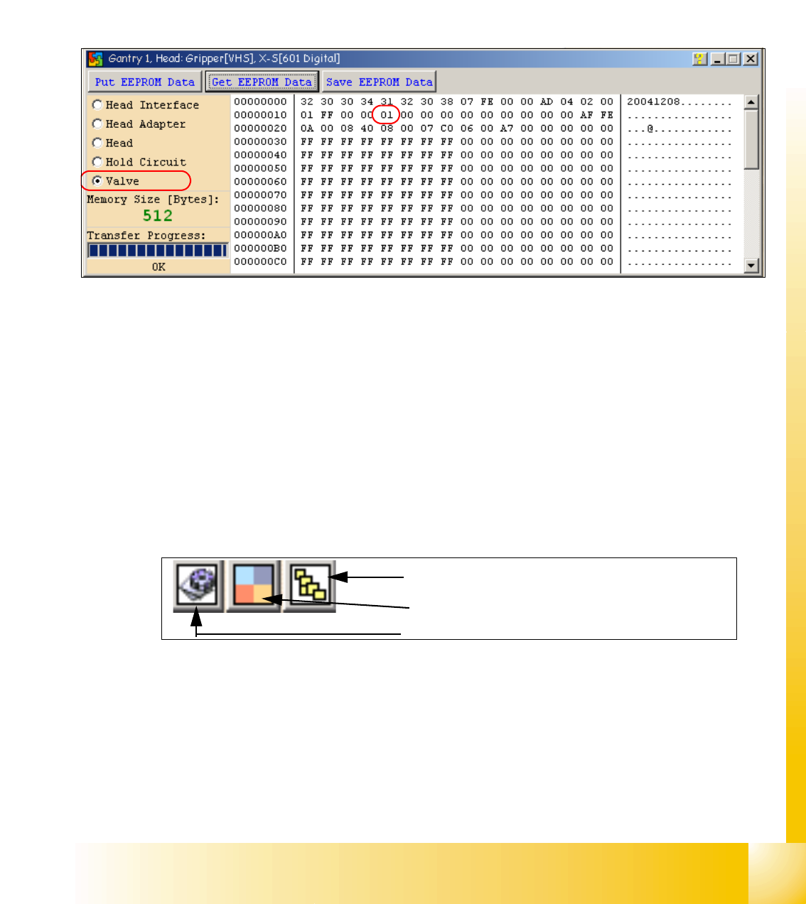
Attention: The vacuum generator digital (C&P20) and thevacuum generator analog (Twin head)
don‘t have a board type ID. In the memory space on the EEPROM stays 00.
Important: Both vacuum generators will be recognized via a device number.
The device number is saved in the memory space 14 on the EEPROM.
Device number ID 01 vacuum generator digital
Device number ID 02 vacuum generator analog
Fig. 3.6 - 10 Device number vacuum generator digital C&P20
3.6.2.2 Read and write the Board type ID with CAN commands
– Switch off the machine.
– Connect the service laptop to the machine CAN bus at PA1 and/or PA2.
Make sure that the cable is connected to channel 1 for PA1 and that, at least the transmitter is
connected to channel 2 of the Kvaser card.
– Switch on the machine
– Start the "CACCIA" software and check the machine configuration with Caccia.
– Doubleclick to open the subsystem control center.
Fig. 3.6 - 11 Icons: properties, machine configuration, subsystem control center
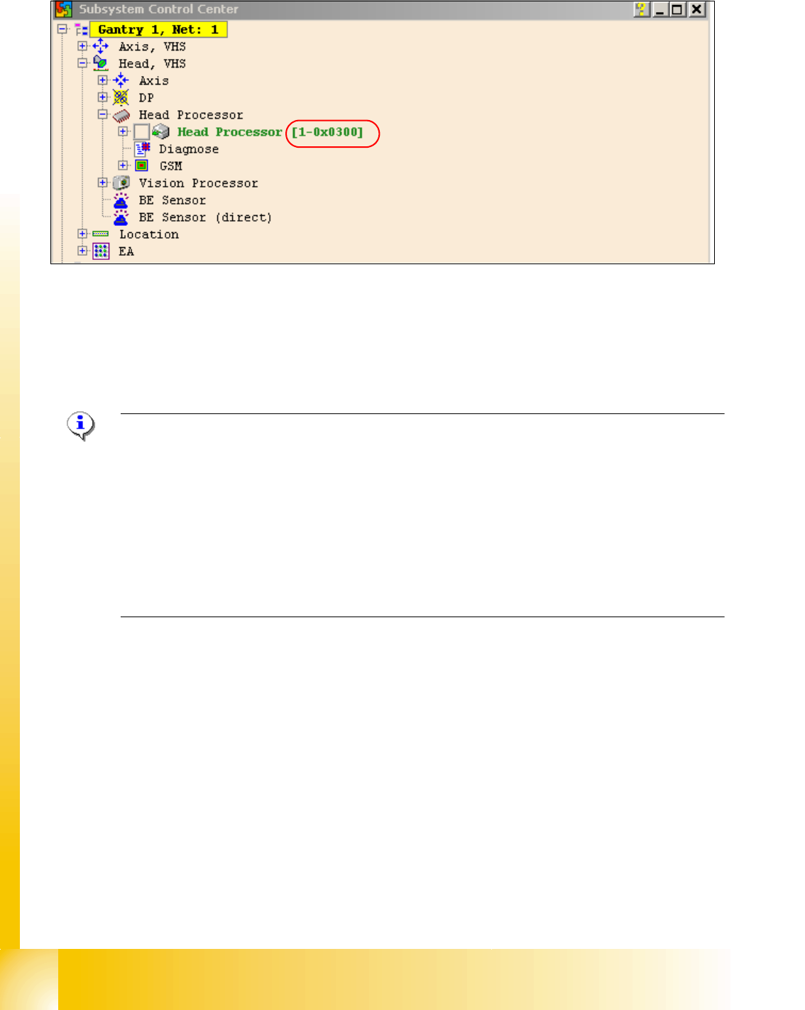
–Click on the "Get Versions" button.
The system will display all available subsystems with their firmware versions and CAN IDs.
Subsystem control center
Machine configuration window
Properties (settings, restart Kvaser card)
1 - 70
Student Guide SIPLACE X
3 Communication and Control Edition 09/2005
70
Fig. 3.6 - 12
– Look for the right CAN ID in the Subsystem Control Center depending on the error and use this
CAN ID to work in the network windows.
– This means, for check the Head interface, Head adapter and Intermediate distributor use the
CAN ID 300 for Gantry 1 or 308 for Gantry 2 and so on.
Note: Please use always the ID‘s, which you get if you press the Button " GET VERSION or AC-
TIVATE ID‘s" in the Subsystem Control window.
e.g. Head Processor: Portal 1 --> 300
Portal 2 --> 308
Portal 3 --> 310
Portal 4 --> 318
Exception: If you don‘t received a message from a subsystem, so you can try to work with "Stan-
dard ID‘s" e.g.Head processor: Gantry 1 --> 304 / Gantry 2 --> 30C / Gantry 3 --> 314 / Gantry
4 --> 31C 3
– If you want to write Board type ID‘s with CAN commands, it is necessary, that the TQM module
is running with the BIOS only!
– At first, carry out the BIOS download on the TQM module, thus you are sure that the TQM mo-
dule is running in the BIOS only.
– Open the network 1 for PA 1 and network 2 to for PA 2.
– With the right CAN ID and the CAN commands you can write the correct ID in the EEPROM.
1 - 71
Student Guide SIPLACE X
Edition 09/2005 3 Communication and Control
71
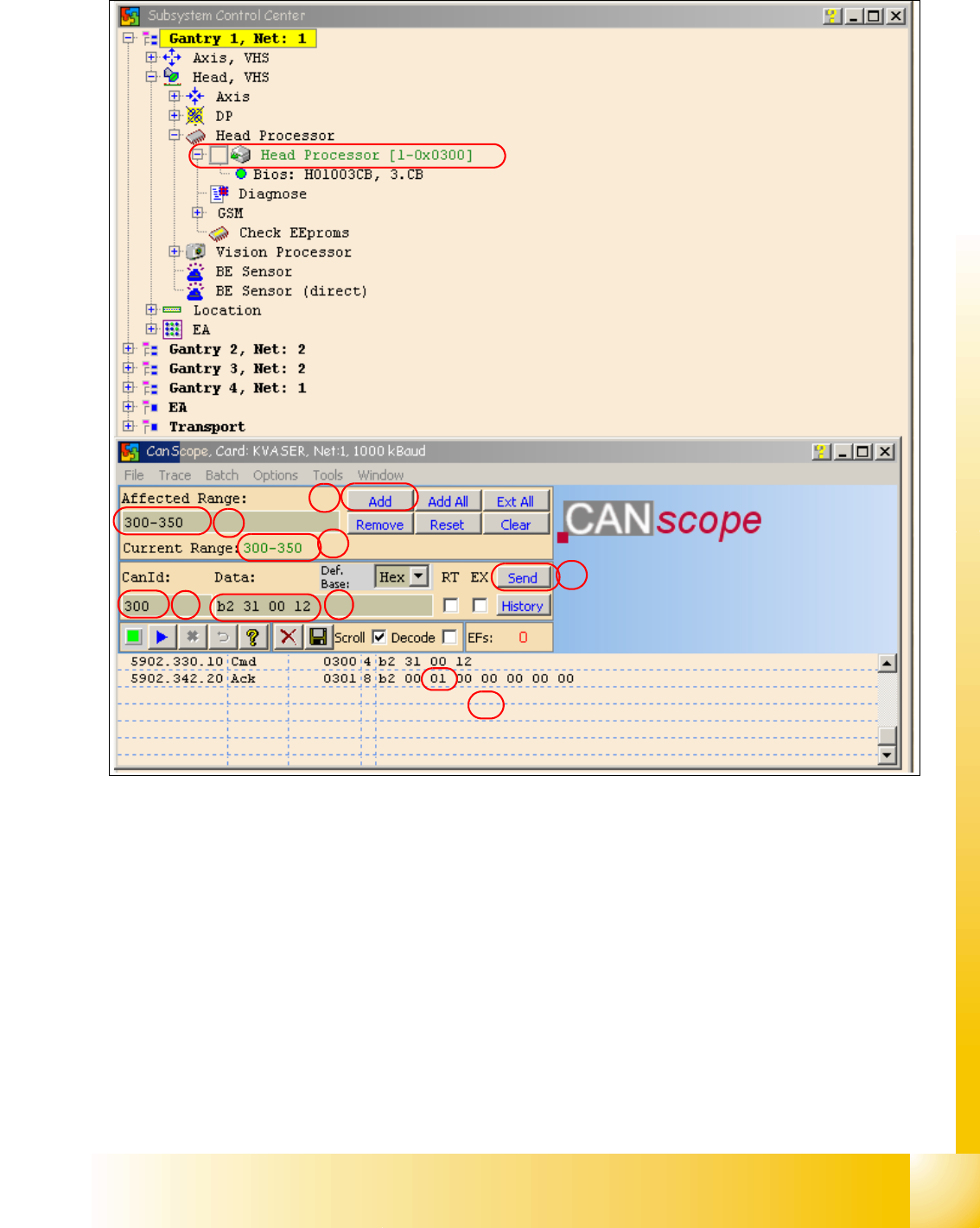
Fig. 3.6 - 13 Read the board type ID Head interface
(1) Reduce the range of CAN ID‘s.
- Write under "Affected Range" a small area of CAN ID‘s, to reduce the counter of CAN Bus
commands which appears in the network window.
- Confirm with "Add"
- The CAN ID Range will be show under "Current Range".
(2) Write the "Can ID" in the field "CanId".
(3) Write under "Data" the CAN Command.
e.g.. b2 31 00 120 b2 --> read EEPROM
31 --> read from headinterface
12 --> memory place in the memory (hex).
1a
1b
1c
2
3
4
5