SiplaceX4_en.pdf - 第154页
1 - 8 S tudent Guide SIPLACE X 4 Services to the machine Edition 09/2005 8 4.2.4 Power Supply Unit The main power supply unit is mounted on a comp act slide-in module, and located on the left side of the middle section. …
1 - 7
Student Guide SIPLACE X
Edition 09/2005 4 Services to the machine
7
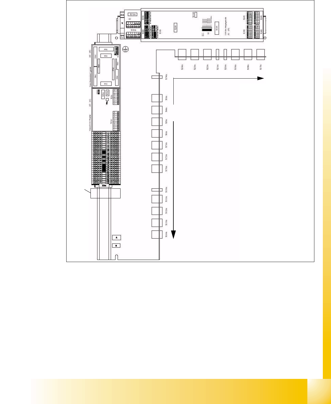
4.2.3 Sub distribution Unit, section 4
Fig. 4.2 - 3 section 4, sub distributor
Legend:
1. Terminal block X1ra ((GND,+5V,+15V,-15V,+24V,+52V, various signals)
2. DC/DC distributor for PCB camera (for stationary cameras future application) on placement
area 1
3. Vision illumination control board for stationary cameras placement area 1 (future application).
4. CAN I/O module (SLIO)
5. Connector bar (connector X3ra - X6ra, X71ra-X74ra, X10ra - X24ra)
6. 8-fold AND operation for safety loop (A5)
52
3
1
4
6
1 - 8
Student Guide SIPLACE X
4 Services to the machine Edition 09/2005
8
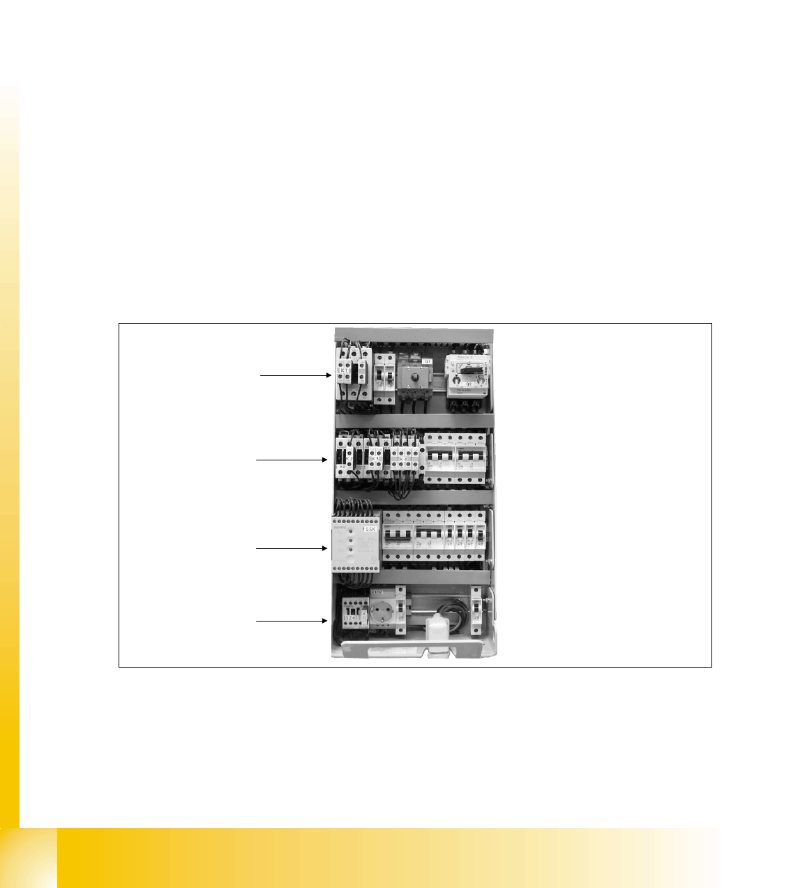
4.2.4 Power Supply Unit
The main power supply unit is mounted on a compact slide-in module, and located on the left
side of the middle section. When viewed from the outside only the red main power switch is visi-
ble.
A lockable door prevents access to the unit.
With the open cover, the state of the following protective devices can be quite easily monitored.
– Motor circuit breaker
– Main contactor
–Safety relay
– Power circuit breaker
With the lockable door open, the state of all circuit breaker, contactor and the condition of the
safety combination (SSK) can be easily monitored to access the power supply for country
specific installment:
1. Unlock the interlock device
2. Slide out the module
3. Reconfigure for country specific power
r
Fig. 4.2 - 4 main power unit
For operating the SIPLACE X, a 3 phase alternating power is supplied. ’N’ is only used for the ser-
vice socket. The contacts L1/L2/L3/N/PE are below the main power module. The separate pro-
tected fuse F1 is crotched before the power filter (1 phase (L3)).
SSK
K5
K2, K3, K4
K1

1 - 9
Student Guide SIPLACE X
Edition 09/2005 4 Services to the machine
9
Units Identification Contact Voltages
X100 main power supply L1, L2, L3 3 x 204 VAC / 3 x 380 VAC
3 x 400 VAC / 3 x 415 VAC
X102 service socket
L3, N, PE
115 VAC / 220 VAC / 230 VAC / 240 VAC
Z1 line filter L1, L2, L3 3 x 204 VAC / 3 x 380 VAC
3 x 400 VAC / 3 x 415 VAC
Q1 main switch 1, 3, 5 u.
2, 4, 6
3 x 204 VAC / 3 x 380 VAC
3 x 400 VAC / 3 x 415 VAC
Q2 motor circuit breaker 1, 3, 5 u.
2, 4, 6
3 x 204 VAC / 3 x 380 VAC
3 x 400 VAC / 3 x 415 VAC
L20 unloading thrush L1, L2, L3 3 x 204 VAC / 3 x 380 VAC
3 x 400 VAC / 3 x 415 VAC
K1 main contactor 1, 3, 5 u.
2, 4, 6
3 x 204 VAC / 3 x 380 VAC
3 x 400 VAC / 3 x 415 VAC
K2 contactor (voltage built-up
of the intermediate circuit
voltage for X/Y/Star axes)
1, 3, 5 u.
2, 4, 6
3 x 177 VAC
K3 contactor (voltage built-up
of the intermediate circuit
voltage for X/Y/Star axes)
1, 3, 5 u.
2, 4, 6
3 x 177 VAC
K4 contactor (voltage built-up
of the intermediate circuit
voltage for X/Y/Star axes)
1, 3, 5 u.
2, 4, 6
3 x 177 VAC
K5 contactor software release
is ON)
A1(+)– A2 (-)
1, 3, 7 and
2, 4, 8
24VDC
24 VDC to GND
24 VDC to GND
K6 (SSK) safety combination L+, X1,X3, X5
13, 33
23
24 VDC to GND
32VDC to GND
F1 fuse service socket (6A);
1-phase
1, 2 115 VAC / 220 VAC
230 VAC / 240 VAC
F2 fuse co-table (32A);
3-phase
1, 3, 5 u.
2, 4, 6
3 x 36 VAC
F4 fuse (32A) X- / Y-axis;
3-phase.
1, 3, 5 u.
2, 4, 6
3 x 177 VAC
F5 fuse (10A) star-axis;
1-phase
1, 2 145 VDC to GND