SiplaceX4_en.pdf - 第162页
1 - 16 S tudent Guide SIPLACE X 4 Services to the machine Edition 09/2005 16 4.2.5 Power Supply Computer Unit When the main switch is on, th e DC/DC converter in the computer unit is supplie d with 52 VDC by the main pow…
1 - 15
Student Guide SIPLACE X
Edition 09/2005 4 Services to the machine
15
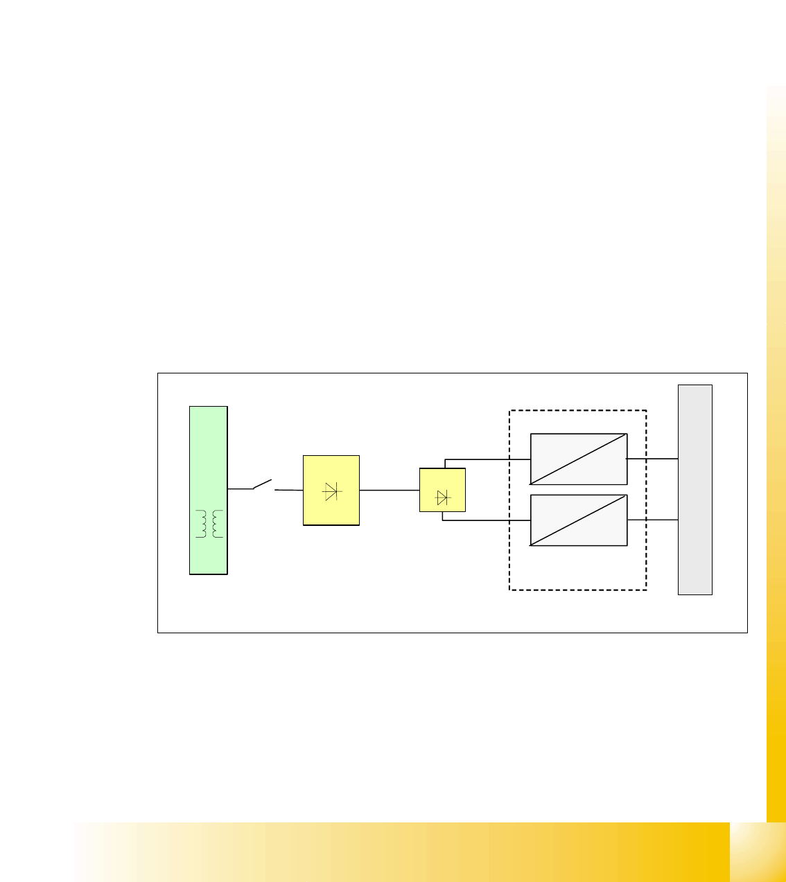
4.2.4.5 DC/DC Converter in Main Power Supply
Two DC/DC converter U20 and U30 generate the +24 VDC and +5 VDC, which are used overall
in the electrical system, are located in the main power supply module.
DC/DC converter U20:
1.+24 VDC converted from 52 VDC is split into 4 path
– path 1: power for servo enable
– path 2: SSK relay K6
– path 3: for inrush current limiter servo
– path 4: mainly used: general use of 24V all over the machine
2.+24 VDC converted from 52 VDC is split into 2 path:
– ventilator for the axis unit
– PCB transport control board
DC/DC converter U30:
5 VDC logic power, which is mainly used in the overall machine
Fig. 4.2 - 8 DC/DC converter main power supply
T1
U7
52 VDC
24 VDC
52 VDC
5 VDC
U6
F10
main power supply distributor
U30
1 - 16
Student Guide SIPLACE X
4 Services to the machine Edition 09/2005
16
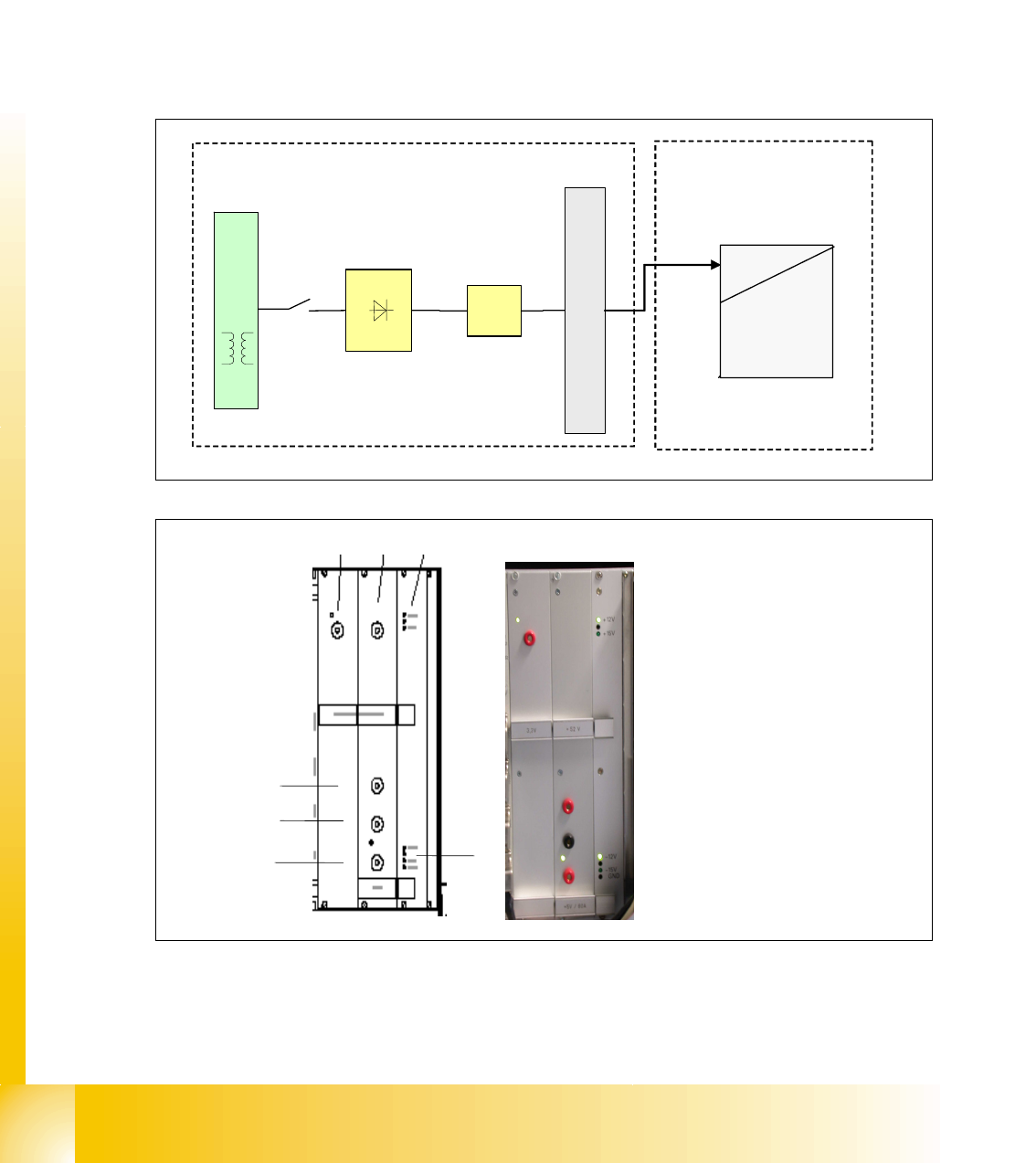
4.2.5 Power Supply Computer Unit
When the main switch is on, the DC/DC converter in the computer unit is supplied with 52 VDC
by the main power supply unit. The following voltages are then generated in the control unit:
4
+ 3.3 VDC / 6A to supply the CPU of Machine Controller and CPU of Station Computer. 4
+ 5 VDC / 6A to supply the digital electronic circuits. 4
± 12 VDC to supply the digital electronic circuits. 4
± 15 VDC (not used, LED off) 4
4
4
Fig. 4.2 - 9 DC/DC converter computer unit
power supply
52 VDC
5 VDC
52 VDC
+ 3.3 V
+ 5V/6A
+/- 12V
+/- 15V
GND
U6
T1
U7
F10
power supply main distributor
computer unit
not used: +/- 15V
12 3
4
5
6
7
1. power 3.3 V (CPU)
2. not used
3. LED +12 V (ON) and +15 V (OFF)
4. power +52 V
5. GND
6. power 5 VDC, 6A
7. LED -12 VDC, GND, -15 VD
1 - 17
Student Guide SIPLACE X
Edition 09/2005 4 Services to the machine
17
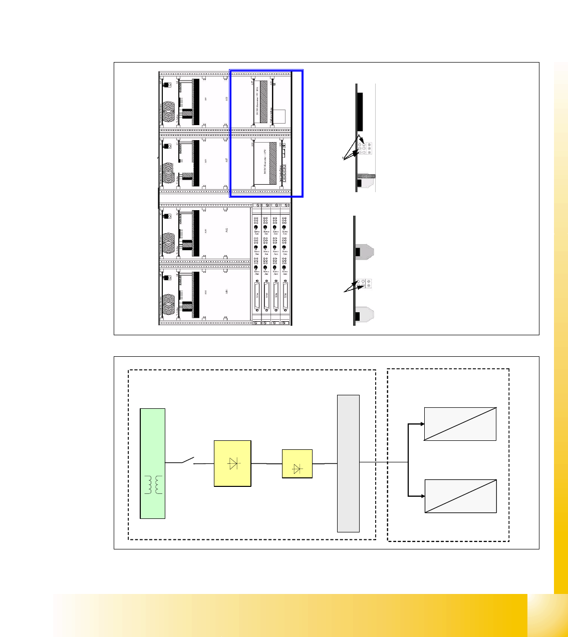
4.2.6 Power Supply Axis Unit
When the main switch is on, the axis unit is supplied with 52 VDC from main power supply via X13
and generates the voltages as shown below.
The +/-15V and 5V supply voltages for the servo unit’s electronic circuits are generated from the
two DC/DC converter, which are integrated in the servo unit. This DC/DC converter generates the
5V and +/- 15V needed for the servo board and the axis controller and the +/-15V are also used
on placement heads and anti-crash, for e.g. it will travel to main distributor X4qa (sector 2) and
then to terminal block X1qa and get distributed from here.
4
4
4
Fig. 4.2 - 10 DC/DC converter axis unit
1
2
o
o
power supply on top: +-15 / 5V
o
o
o
1
+5V Axis controller
+15V Servo
-15V Servo
GND
2
-15V axis controller and machine
+15V axis controller and machine
power supply bottom: +-15 V
GND
GND
power supply
52 VDC
5 VDC
U6
T1
U7
F10
main power supply distributor
52 VDC
+5 VDC
+/- 15 VDC
52 VDC
+/-15 VDC
2
1
axis unit