SiplaceX4_en.pdf - 第164页
1 - 18 S tudent Guide SIPLACE X 4 Services to the machine Edition 09/2005 18 4.2.7 DC/DC Converte r Vision section 2 This DC/DC converter is onl y used for generating 42 V for P&P camera illumi nation as well as the …
1 - 17
Student Guide SIPLACE X
Edition 09/2005 4 Services to the machine
17
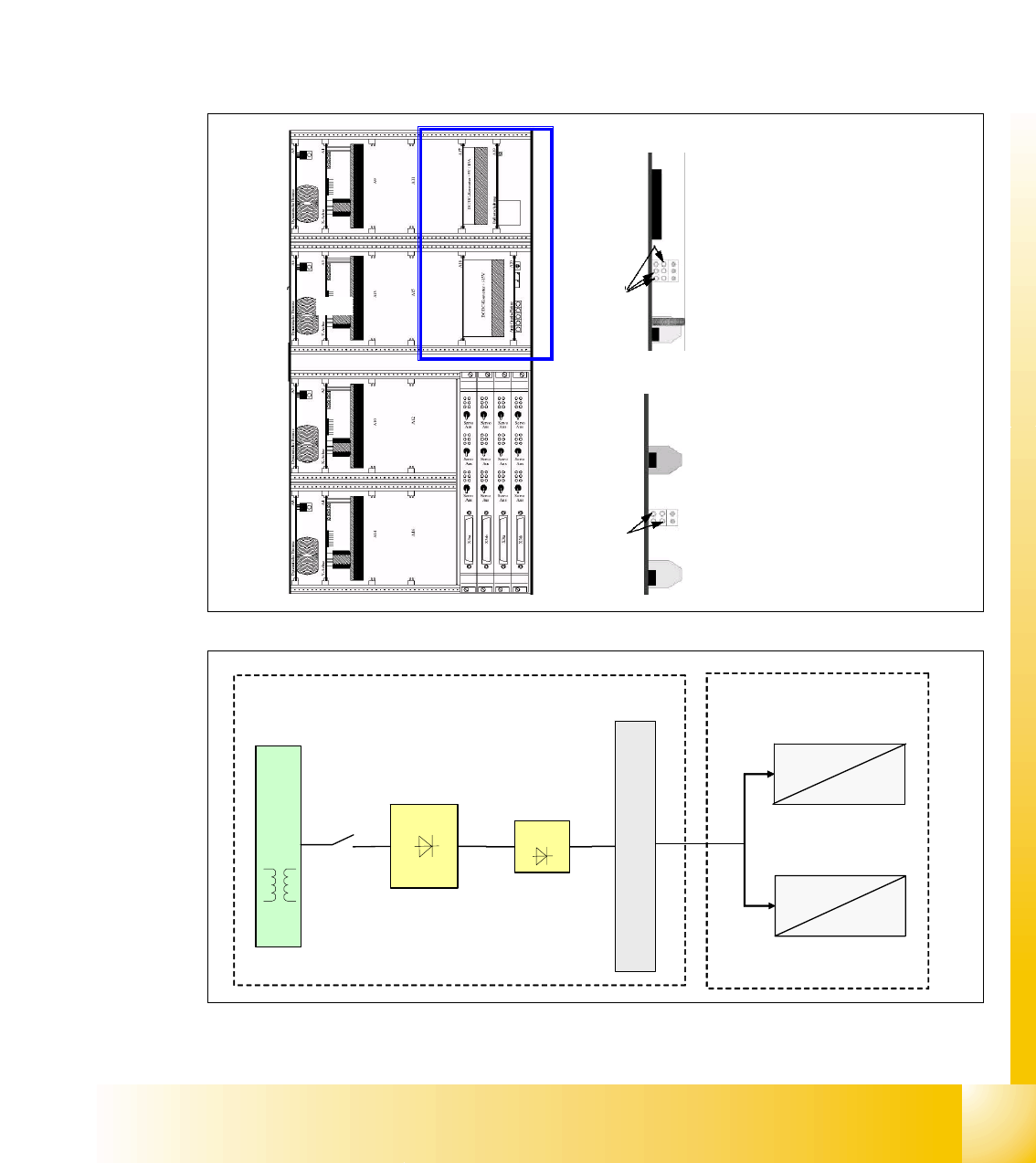
4.2.6 Power Supply Axis Unit
When the main switch is on, the axis unit is supplied with 52 VDC from main power supply via X13
and generates the voltages as shown below.
The +/-15V and 5V supply voltages for the servo unit’s electronic circuits are generated from the
two DC/DC converter, which are integrated in the servo unit. This DC/DC converter generates the
5V and +/- 15V needed for the servo board and the axis controller and the +/-15V are also used
on placement heads and anti-crash, for e.g. it will travel to main distributor X4qa (sector 2) and
then to terminal block X1qa and get distributed from here.
4
4
4
Fig. 4.2 - 10 DC/DC converter axis unit
1
2
o
o
power supply on top: +-15 / 5V
o
o
o
1
+5V Axis controller
+15V Servo
-15V Servo
GND
2
-15V axis controller and machine
+15V axis controller and machine
power supply bottom: +-15 V
GND
GND
power supply
52 VDC
5 VDC
U6
T1
U7
F10
main power supply distributor
52 VDC
+5 VDC
+/- 15 VDC
52 VDC
+/-15 VDC
2
1
axis unit
1 - 18
Student Guide SIPLACE X
4 Services to the machine Edition 09/2005
18
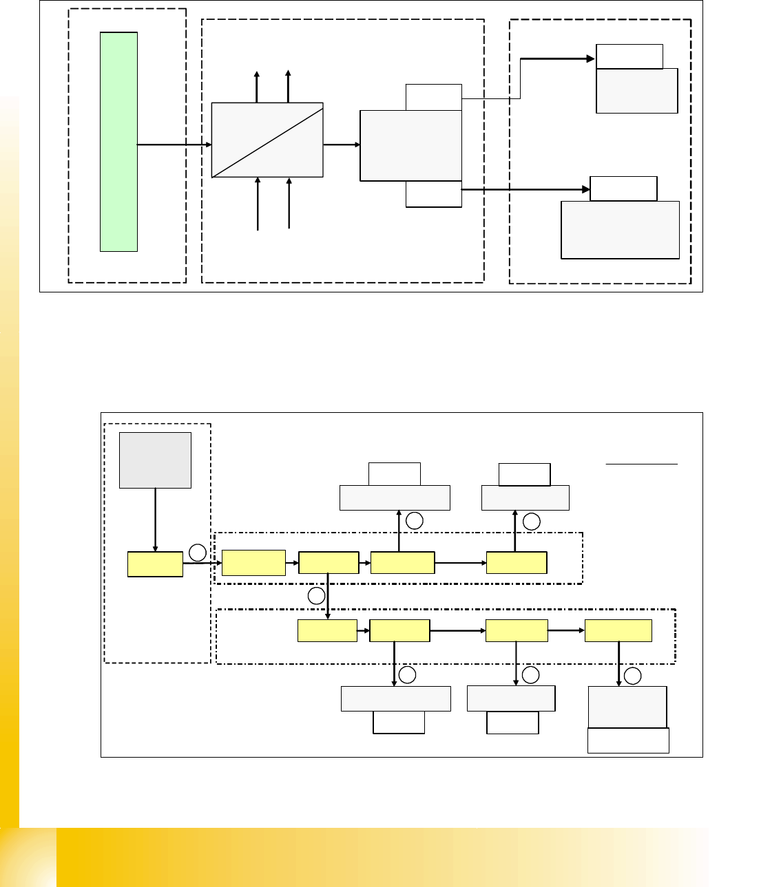
4.2.7 DC/DC Converter Vision section 2
This DC/DC converter is only used for generating 42 V for P&P camera illumination as well as the
power distribution for PCB camera (5/24V) and component camera (24V).
Fig. 4.2 - 11 DC/DC converter section 2
4.2.7.1 Power Supply Tape Cutter
The tape cutter are arranged in a parallel and a serial mode. The tape cutter in sector 2 and sector
3 are serial, tape cutter in sector 1 and sector 4 are also arranged in serial mode.
Fig. 4.2 - 12 power supply tape cutter
52 VDC
42 VDC
m
a
i
n
p
o
w
e
r
s
u
p
p
l
y
d
i
s
t
r
i
b
u
t
o
r
5/24 V for PCB &
component-camera
52V
5/24V
42 V
vision
control
unit
stationary
camera 1
stationary
camera 2
(optional)
main-distributor, section 2
placement area 2
X4qd
X5qd
X5bm
03003439
X5cm
03003440
X2qa_6
X71qa_6 X22qa_4
tape cutter 3
X17qa_4
tape cutter 2
SSK
X16_6
X71ra_6 X22ra_4
tape cutter 4
X17ra_4
tape cutter 1
X21ra_1
2
4
V
Power supply
tape cutter
main valve
X60
main distributer, section 2
sub distributer, section 4
1
2
3
4
5
1 03002505
2 03002519
3 03002530
4 03002534
5 03002541
6 03002546
7 03002545
6
7
X122
X132
X112
X142
cable terms :
1 - 19
Student Guide SIPLACE X
Edition 09/2005 4 Services to the machine
19
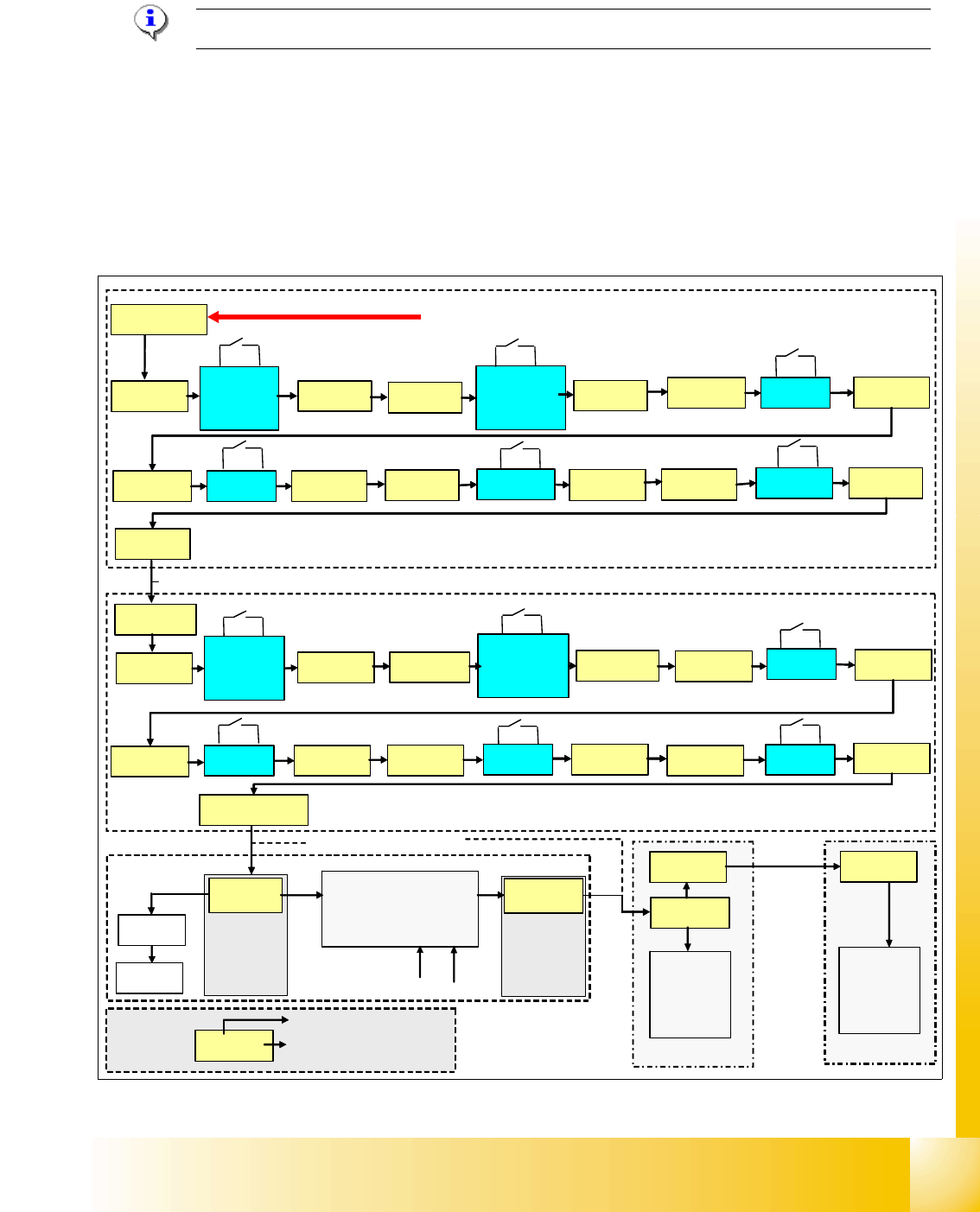
4.2.8 Safety and Control Loop
Please Note: For machine type A you consult the enclosed circuit diagrams.
4.2.8.1 Emergency Stop Loop (safety loop)
Following contacts are switched in serial and build the safety loop: _ 4
– 4 protective cover switches (main cover).
– conveyor cover switch.
– contact on component change over table
– emergency stop button must be released
(input & output conveyor)
Fig. 4.2 - 13 safety loop
security loop START
sub distributer, section 4
main distributer, section 2
24 V
X1ra_19-24
cover
PCB-
input
X11ra_3X11ra_2
cover 1 X13ra_3X13ra_2
cover 4
X14ra_3
X14ra_2
table 1
X18ra_4X18ra_3
table 4
X23ra_4
X23ra_3
X72qa_6
cover
PCB-
output
X11qa_3
X11qa_2
emergency
stop button
output
X12qa_3
X12qa_2
cover 2
X13qa_3
X13qa_2
cover 3 X14qa_3
X14qa_2
table 2 X18qa_4
X18qa_3
table 3
X23qa_4
X23qa_3
X16_4
K5
X2qa_12
X73qa_9
sub, sec. 2
main, sec. 4
24 V
power supply
SSK
24 V
24 V
24 V
electrical isolation
(optical coupler)
GND
Input
Input
X16_12
&
d
i
s
t
r
i
b
u
t
e
r
d
i
s
t
r
i
b
u
t
e
r
emergency
stop button
input
X12ra_3
X12ra_2
X72ra_6
cable term : 03002520
X2qa_4
cable term : 03002505
X8-21
X8-23
X3qb_1
CAN
I/O
X3rb_1
CAN
I/O
X73ra_9
03002521
Example:
X14qa_2
connector
wire on connector