SiplaceX4_en.pdf - 第165页
1 - 19 S tudent Guide SIPLACE X Edition 09/2005 4 Servic es to the machine 19 4.2.8 Safety and Control Loop Please Note: For machine typ e A you consult the enclosed circuit diagra ms. 4.2.8.1 Emergency S top Loop (safet…
1 - 18
Student Guide SIPLACE X
4 Services to the machine Edition 09/2005
18
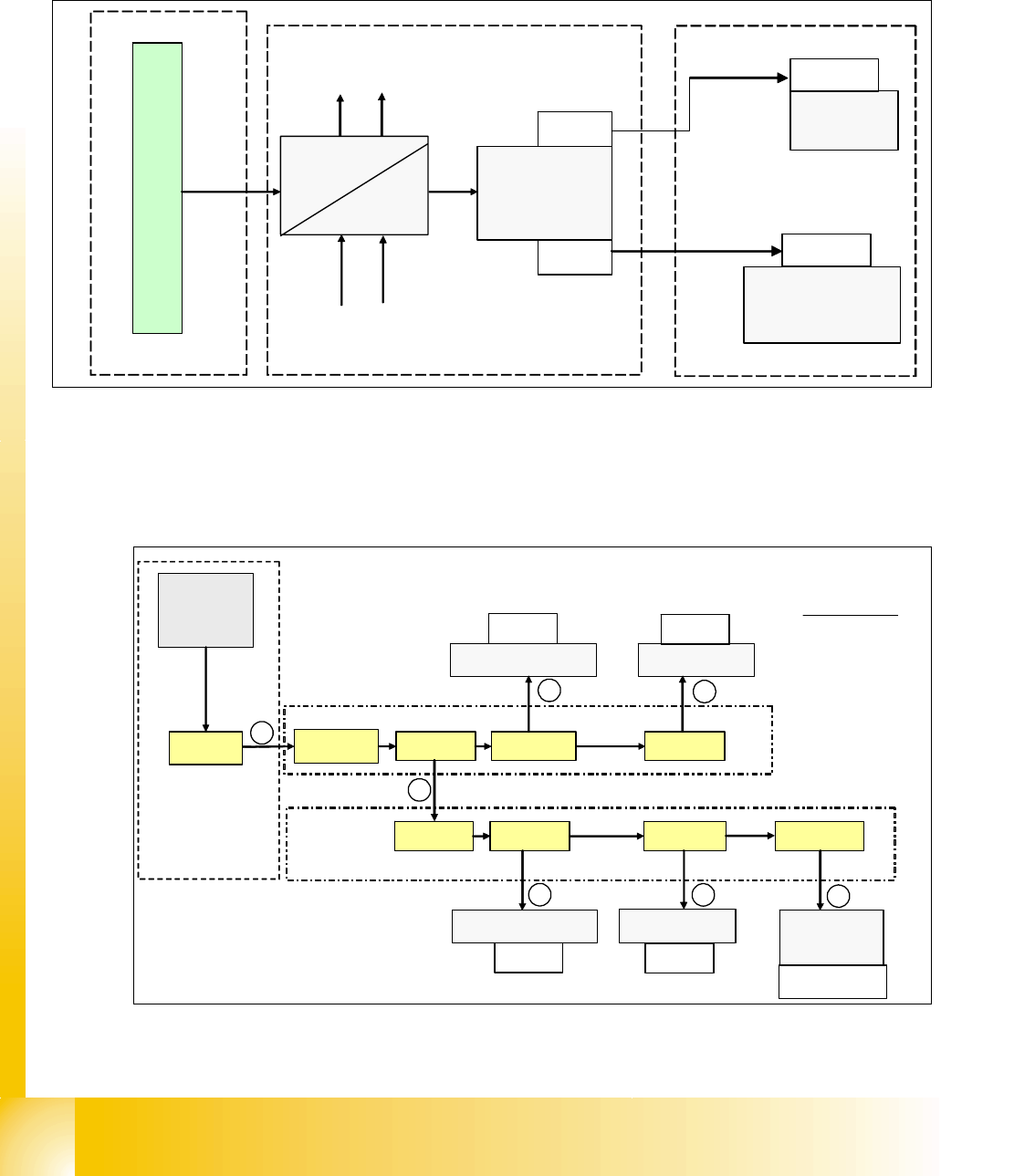
4.2.7 DC/DC Converter Vision section 2
This DC/DC converter is only used for generating 42 V for P&P camera illumination as well as the
power distribution for PCB camera (5/24V) and component camera (24V).
Fig. 4.2 - 11 DC/DC converter section 2
4.2.7.1 Power Supply Tape Cutter
The tape cutter are arranged in a parallel and a serial mode. The tape cutter in sector 2 and sector
3 are serial, tape cutter in sector 1 and sector 4 are also arranged in serial mode.
Fig. 4.2 - 12 power supply tape cutter
52 VDC
42 VDC
m
a
i
n
p
o
w
e
r
s
u
p
p
l
y
d
i
s
t
r
i
b
u
t
o
r
5/24 V for PCB &
component-camera
52V
5/24V
42 V
vision
control
unit
stationary
camera 1
stationary
camera 2
(optional)
main-distributor, section 2
placement area 2
X4qd
X5qd
X5bm
03003439
X5cm
03003440
X2qa_6
X71qa_6 X22qa_4
tape cutter 3
X17qa_4
tape cutter 2
SSK
X16_6
X71ra_6 X22ra_4
tape cutter 4
X17ra_4
tape cutter 1
X21ra_1
2
4
V
Power supply
tape cutter
main valve
X60
main distributer, section 2
sub distributer, section 4
1
2
3
4
5
1 03002505
2 03002519
3 03002530
4 03002534
5 03002541
6 03002546
7 03002545
6
7
X122
X132
X112
X142
cable terms :
1 - 19
Student Guide SIPLACE X
Edition 09/2005 4 Services to the machine
19
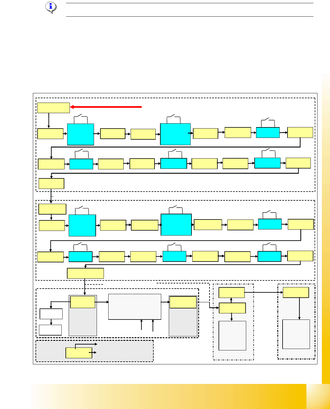
4.2.8 Safety and Control Loop
Please Note: For machine type A you consult the enclosed circuit diagrams.
4.2.8.1 Emergency Stop Loop (safety loop)
Following contacts are switched in serial and build the safety loop: _ 4
– 4 protective cover switches (main cover).
– conveyor cover switch.
– contact on component change over table
– emergency stop button must be released
(input & output conveyor)
Fig. 4.2 - 13 safety loop
security loop START
sub distributer, section 4
main distributer, section 2
24 V
X1ra_19-24
cover
PCB-
input
X11ra_3X11ra_2
cover 1 X13ra_3X13ra_2
cover 4
X14ra_3
X14ra_2
table 1
X18ra_4X18ra_3
table 4
X23ra_4
X23ra_3
X72qa_6
cover
PCB-
output
X11qa_3
X11qa_2
emergency
stop button
output
X12qa_3
X12qa_2
cover 2
X13qa_3
X13qa_2
cover 3 X14qa_3
X14qa_2
table 2 X18qa_4
X18qa_3
table 3
X23qa_4
X23qa_3
X16_4
K5
X2qa_12
X73qa_9
sub, sec. 2
main, sec. 4
24 V
power supply
SSK
24 V
24 V
24 V
electrical isolation
(optical coupler)
GND
Input
Input
X16_12
&
d
i
s
t
r
i
b
u
t
e
r
d
i
s
t
r
i
b
u
t
e
r
emergency
stop button
input
X12ra_3
X12ra_2
X72ra_6
cable term : 03002520
X2qa_4
cable term : 03002505
X8-21
X8-23
X3qb_1
CAN
I/O
X3rb_1
CAN
I/O
X73ra_9
03002521
Example:
X14qa_2
connector
wire on connector
1 - 20
Student Guide SIPLACE X
4 Services to the machine Edition 09/2005
20
Description safety loop: 4
If the emergency stop loop is closed, 24 V will be present on K5, contact 3. Another 24 V signal
is activated at each CAN I/O module as
’emergency stop loop OK’ and signalize that all covers
are closed and table connected.
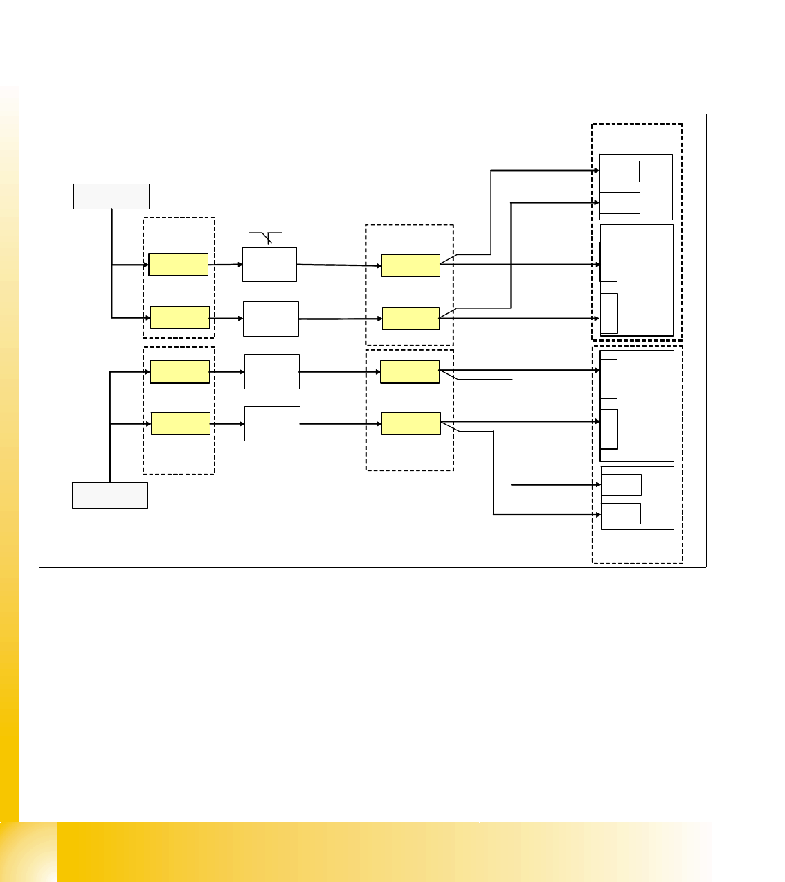
4.2.8.2 Control loop
Component Table Loop 4
The 4 component tables are switched in parallel mode. If 1 or more table is not connetcted, the
contact is closed and the 24V signal is set on the CAN I/O module in section 2 and shows which
component table is not connected.
Fig. 4.2 - 14 component table loop
24V
X18ra_7
co-table
1
M_co-table 1
C
A
N
I
/
O
m
o
d
u
l
e
s
e
c
t
i
o
n
2
X23ra_7
co-table
4
X23qa_7
co-table
3
M_co-table 3
X18qa_7
co-table
2
M_co-table 2
X23qa_2
X18qa_2
X1ra_24V
24V
24V
24V
M_co-table 4
X1qa_24V
input
main, section
2
sub, section
4
main, section
2
X23ra_2
X18ra_2
C
A
N
I
/
O
m
o
d
u
l
e
s
e
c
t
i
o
n
4
X5rb_3
X5rb_7
X5qb_7
X5qb_3
8-fold
AND
8-fold
AND
X1re_3
X1re_7
X1qe_3
X1qe_7
sub, section
4
sub, section
4
main, section
2