SiplaceX4_en.pdf - 第169页
1 - 23 S tudent Guide SIPLACE X Edition 09/2005 4 Servic es to the machine 23 St art Button Loop 4 The star t button loop consists of 6 contacts and the y are switched in par allel mode . If 1 ore more star t button is p…
1 - 22
Student Guide SIPLACE X
4 Services to the machine Edition 09/2005
22
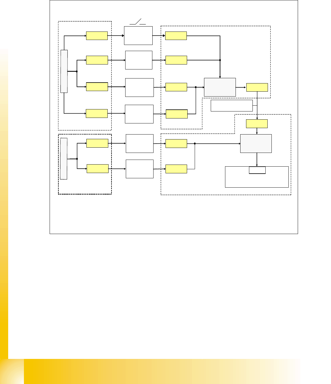
Stop Button Loop 4
The stop button loop consists of 6 contacts which are switched in parallel mode.
If 1 ore more stop button is pressed, the contact is closed and the 24 V signal sets an input on
CAN I/O module in section 4 and shows, that any stop button is pressed.
Fig. 4.2 - 16 stop button loop
24V
stop button
PCB- output
right
stop button
PCB- output
left
X1qa_stopbutton
stop button
PCB- input
right
X11qa_1
X12qa_1
X11ra_1
X
1
q
a
_
2
4
V
24V
24V
X73qa_2
X73ra_2
stop button
right
(pneumatic)
X10qa_1
24V
stop button
PCB- input
left
X12ra_1
X
1
r
a
_
2
4
V
X10qa_3
X11qa_6
X12qa_6
X11ra_6
X12ra_6
stop button
left
(power supply)
X9qa_1 X9qa_3
X1ra_stopbutton
C
A
N
I
/
O
-
m
o
d
u
l
e
s
u
b
d
i
s
t
r
i
b
u
t
e
r
,
s
e
c
t
i
o
n
4
3
4
Eingang
cable term : 03002521
X4rb_2
sub distributer, section 4
main distributer, section 2
main distributer, section 2
sub distributer, section 4
1 - 23
Student Guide SIPLACE X
Edition 09/2005 4 Services to the machine
23
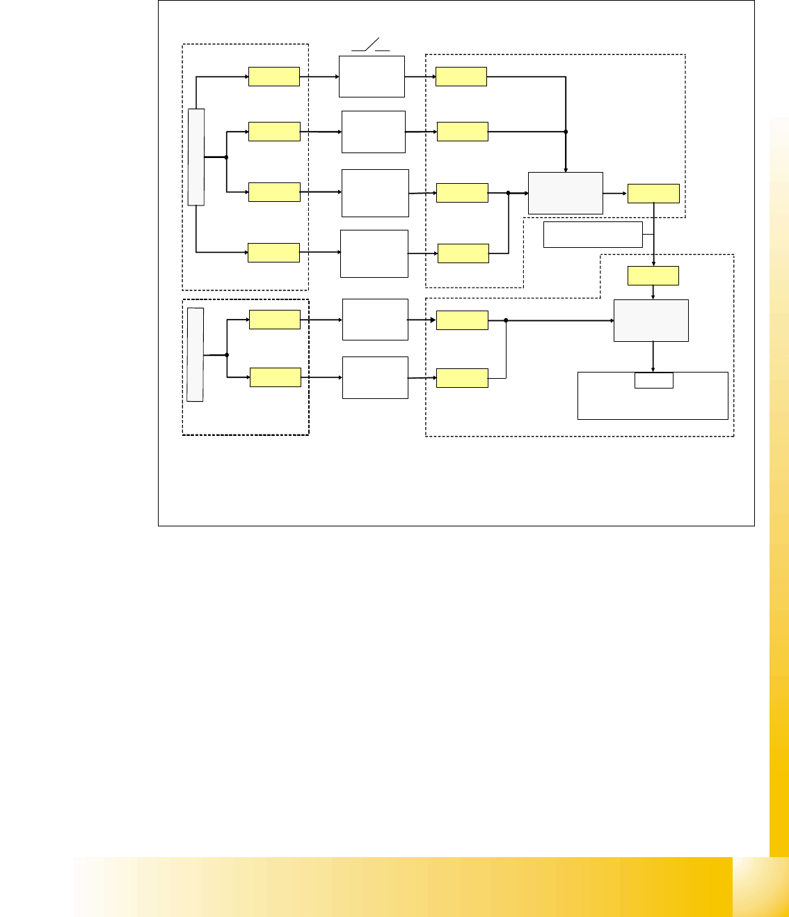
Start Button Loop 4
The start button loop consists of 6 contacts and they are switched in parallel mode.
If 1 ore more start button is pressed, the contact is closed and the 24 V signal sets an input on
CAN I/O module in section 4 and shows, that any start button is pressed.
Fig. 4.2 - 17 start button loop
24V
stop button
PCB- output
right
stop button
PCB- output
left
X1qa_startbutton
start button
PCB- input
right
X11qa_1
X12qa_1
X11ra_1
X
1
q
a
_
2
4
V
24V
24V
X73qa_1
X73ra_1
start button
right
(pneumatic)
X10qa_1
24V
X12ra_1
X
1
r
a
_
2
4
V
X10qa_2
X11qa_5
X12qa_5
X11ra_5
X12ra_5
start button
left
(power supply)
X9qa_1 X9qa_2
X1ra_startbutton
C
A
N
I
/
O
-
m
o
d
u
l
e
s
u
b
d
i
s
t
r
i
b
u
t
e
r
,
s
e
c
t
i
o
n
4
3
4
Eingang
cable term: 03002521
X4rb_1
sub distributer, section 4
main distributer, section 2
sub distributer, section 4
main distributer, section 2
start button
PCB- input
left

1 - 24
Student Guide SIPLACE X
4 Services to the machine Edition 09/2005
24
4.2.8.3 How does the emergency stop loop work?
The placement system cannot be used in placement mode until all the supply voltages have been
enabled by the protective circuit. The following conditions must also be fulfilled:
4
– All four component change-over tables must be docked.
– All covers must be closed.
– Both emergency stop push-buttons must be released.
– The minimum air pressure must be present.
– The software enable signal must be ready.
– The Message ’
Security Loop OK’ must be sent (for GND on X6 on SSK, CAN I/O output)
– 24 V must be present at the start button.
After the start button is pressed, the SSK combinaton activates the following voltages
: _ 4
– secundary circuit 250 V for servo X/Y axis (via K2, K3, K4).
– secundary circuit 150 V for star axis.
– servo unit receives ’Servo Enable’ signal for servo amplifier (K4.5)
– The message
’Ctrl_On’ must be sent to CAN I/O (24V from axis unit after receiving the
’servo enable)
– 34 V operating voltage for the transport handling.
– 24 V operating voltage for the tape cutter.
– M_X/Y: +24 V for K3 and K4
– M_tape cutter: +24 V for K2