SiplaceX4_en.pdf - 第173页
1 - 27 S tudent Guide SIPLACE X Edition 09/2005 4 Servic es to the machine 27 4.2.10 V arious Signal 4.2.10.1 Sof tware Release (Software Enabled) The software rele ase signal is given by the CAN I/O card when the machin…

1 - 26
Student Guide SIPLACE X
4 Services to the machine Edition 09/2005
26
How is SSK K6 energized? 4
If the safety covers are closed, the emergency stop circuit intact and K5 closed, 24 V is supplied
to terminal X1, X3 and X4, when GND is given on contact 6 (X6) from Message ’security loop OK’
and when a start button is pressed. This voltage allows K1' to be energized and when it's contacts
close then K2' and K3' can energize. As soon as these relays energize, K1' is de-nergized how-
ever K2' and K3' now remain energized due to their contacts providing a self latching facility.
Pressing the ON Button 4
Assuming the ON button is pressed: 24 V is activated and will split into 2 paths.
– 1st path: 24V is activated at the CAN I/O module 1. The signal from this module activates
the CAN bus to notify the Machine Controller that the ON button is pressed; this should dis-
able the Press Start Key message.
– 2nd path: 24V is activated at the power supply main distributor X16_2, from here, this
signal (On Button) is activated at K1.4 (closed when main switch On), K2.4 (NC), K3.4 (NC),
K4.4 (NC), K5 (NO) and at last at pin 6 of SSK.
The 24 V is activated when the following conditions are met:
4
When the machine controller gets the signal (1st path) ’START BUTTON pressed’, it will
through the CAN I/O module set an output and proceed to A1 of contactor K5 to energize
K5 (C_Software_On)
4
So when K5 is energized, the signal from 2nd path will flow to X4 of the SSK. 4
4.2.9.1 How does the SSK latch?
Condition: When K5 is energized, the following will happen: 4
– L+ will get 24 V and will light up the first LED
– Since L+ and X1 are internally connected, this 24 V signal will be fed back from X1 to the
CAN I/O module as a SSK READY signal to the MC.
– The X4 on SSK will have 24 V temporary (only when ON is pressed), but it is enough to
energize K1' internal of the SSK. When K1’ is energized, K2' and K3' will also be energized
internally of SSK - only if X3 and X5 of SSK has 24 V with them.
How does X3 and X5 of SSK get the 24V?
– If all covers closed, feeder table locked on, E_Stop released - a 24 V will pass as the emer-
gency loop signal to K5 pin 3 and 4. It proceeds then to X3 and X 5 of SSK.
How does X14 and X34 get hte 24 V?
– When K2' and K3' are latched inside the SSK, pin 34 of SSK will have 24 V.
Main task of them is to power the tape cutter and to energize K2.
4
– When K2’ and K3’ are latched inside the SSK, pin 14 of SSK will have 24 V.
Main task of it is to energize K3 and K4 (with a slight delay).
1 - 27
Student Guide SIPLACE X
Edition 09/2005 4 Services to the machine
27
4.2.10 Various Signal
4.2.10.1 Software Release (Software Enabled)
The software release signal is given by the CAN I/O card when the machine controller software is
fully booted. This means that not only must the machine controller software be booted but com-
munication must be established to the vision system, axis cards, CAN BUS, station computer and
line computer (unless it is operating in stand-alone mode).
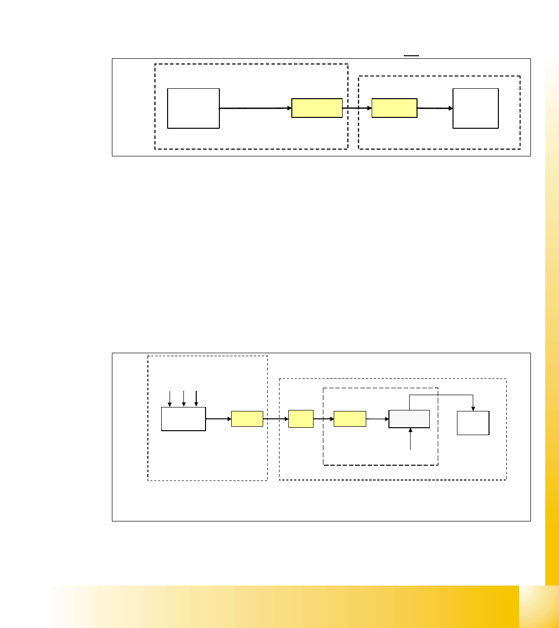
The software release signal is only present on K5, contact A1 when the CAN I/O gives the signal
in combination when the start button is pressed.
If the emergency stop circuit is broken then the software release is
not given.
Fig. 4.2 - 18 software release signal
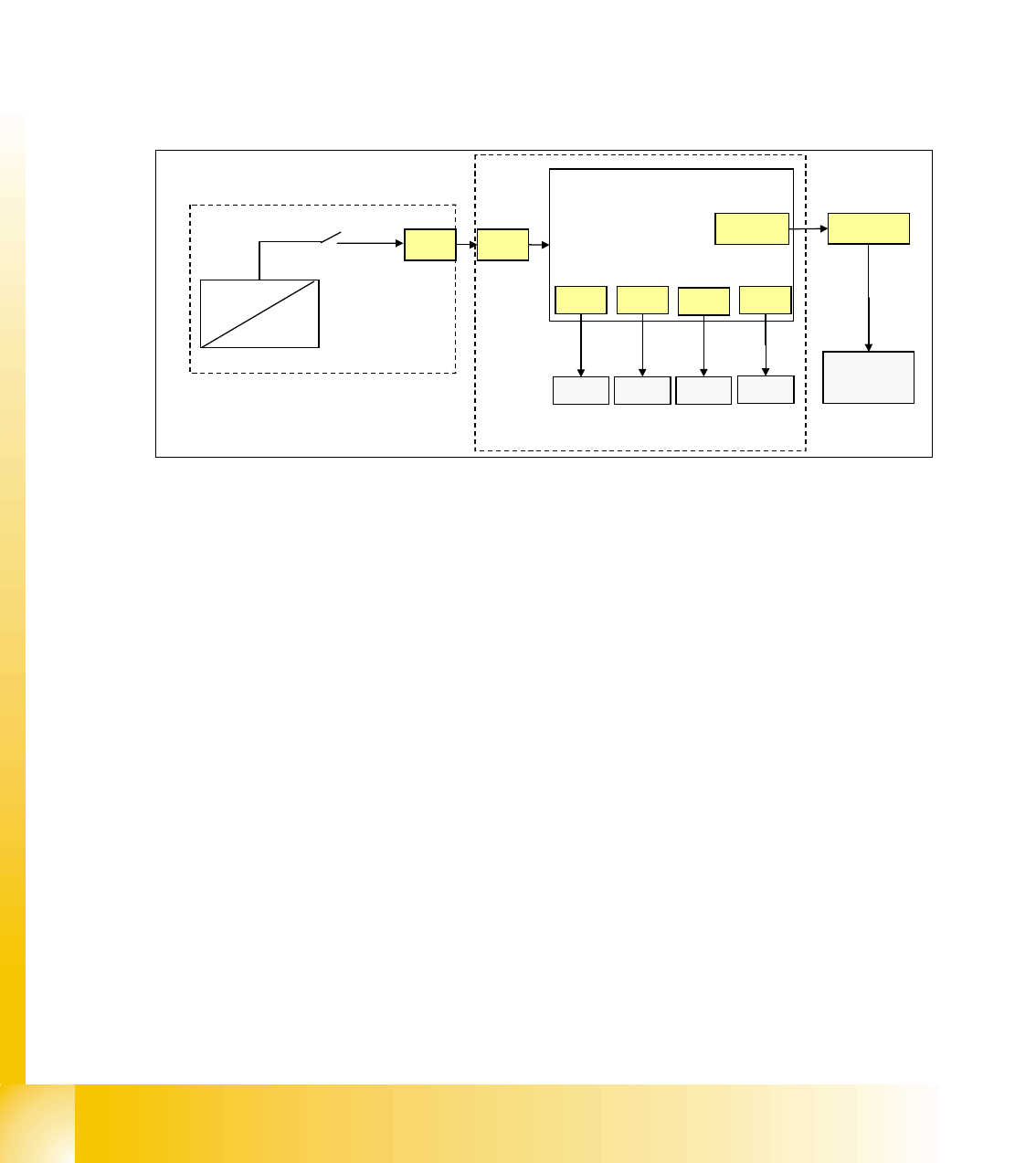
4.2.10.2 Security Loop OK signal
The security loop signal is given by the CAN I/O when following conditions are filled.
Emergency stop loop is closed and in addition, every single safety device send a message to the
CAN I/O module. Inside this module, they are logical matched by using a FPGA and the
CAN I/O set an output 24V ’security messages OK’ which travels to the power supply.
Conditions:
– all covers closed
– all component tables connected
– all emergency stop button released
Fig. 4.2 - 19 signal security loop
This signal runs into the power supply X8-20 and connects GND to SSK, contact X6.
X2qa_5
CAN I/O
24 V
X16_5
K5
contact
A1(+)
power supply
M_software
release
main distributer, section 2
output
CAN I/O
module
X2qa
X16
24 V
X8-20
BTS 117
SSK
X6
GND
GND
M_ covers closed
M_ tables connected
M_stop button released
power supply
1
Legend:
1: BTS 117 power switch for GND
section 2
output
inrush current limiter board
1 - 28
Student Guide SIPLACE X
4 Services to the machine Edition 09/2005
28
4.2.10.3 Control On signal
With energizing the contactor K4 of power supply, the auxillary contact of K4.5 (K4) get closed.
24 V (servo enable signal) is activated at the DC/DC converter to main power supply distributor
X13 to axis unit X21 and to Anti-Crash board.
Here it is split in 2 paths:
path1: 24 V is activated as the
’servo enable signal’ at anti crash board and at the servo board
X/Y axis (via X31, X32, X33, X34) to enable the servo amplifier (switching GND to the servo board
via optical coupler).
path 2: 24 V is activated as the ’
Ctrl_On’ signal at section 2, connector X4qa and at last at the CAN
I/O module as
M_Ctrl_On. The 4 main axis is allowed to move now into any position.
Fig. 4.2 - 20 Control On signal
4.2.11 Power Distribution
The power distrubtion to the different section, gantry and heads is highly structured.
5V and 24 V, generated by DC/DC converter U20 and U30 in main power supply, will first activate
at distributor main power supply, connector X16. Then at section 2, main distributor, connector
X2qa and then at the terminal block X1qa for general use, at connector X71qa and at last at
connector X71ra, section 4.
52 V for camera illumination, generated by U7, is activated at main power supply distributor, X18,
and split into two paths.
path 1: at X18, at section 2, X3qa, at terminal strip X1qa and then 52V is activated at the DC/DC
converter vision for converting the 42 V needed for the IC/FC camera illumination. 52V is also
activated at connector X71qa and connector X71ra in section 4, at X1ra and at last at the DC/DC
distributor vision (42V are not used here)
path 2: (this path is presently not shown in overview and not used) 52V is activated at X18 main
power supply distributor, at section 4, X3ra, at terminal strip X1ra and 52V is also activated at the
DC/DC distributor vision for converting the 42 V needed IC/FC camera illumination in this section.
+/-15 V are generated in the power supply axis unit from 52 V and +/-15V is activated at X4qa and
terminal block X1qa to get distributed for general use. +/-15V is activated at connector X74qa and
X74ra in section 4, sub-distributor (not shown in overview ’power distribution’)
X21
X39wo
X4qa
CAN I/O
section 2
axis unit
anti crash
board
power supply
X13
DC/DC
U20
K4.5
24V
servo
X31 X32
X33
X34
servo
servo servo
M_Ctrl_On
servo enable
input