SiplaceX4_en.pdf - 第192页
1 - 46 S tudent Guide SIPLACE X 4 Services to the machine Edition 09/2005 46 4.3.8.1 Air distribution T win Head 4 Fig. 4.3 - 18 air distribution TWIN-head 4 Legend : 1. sealed 2. air supply TWIN-head segment 1 vacuum-ai…
1 - 45
Student Guide SIPLACE X
Edition 09/2005 4 Services to the machine
45
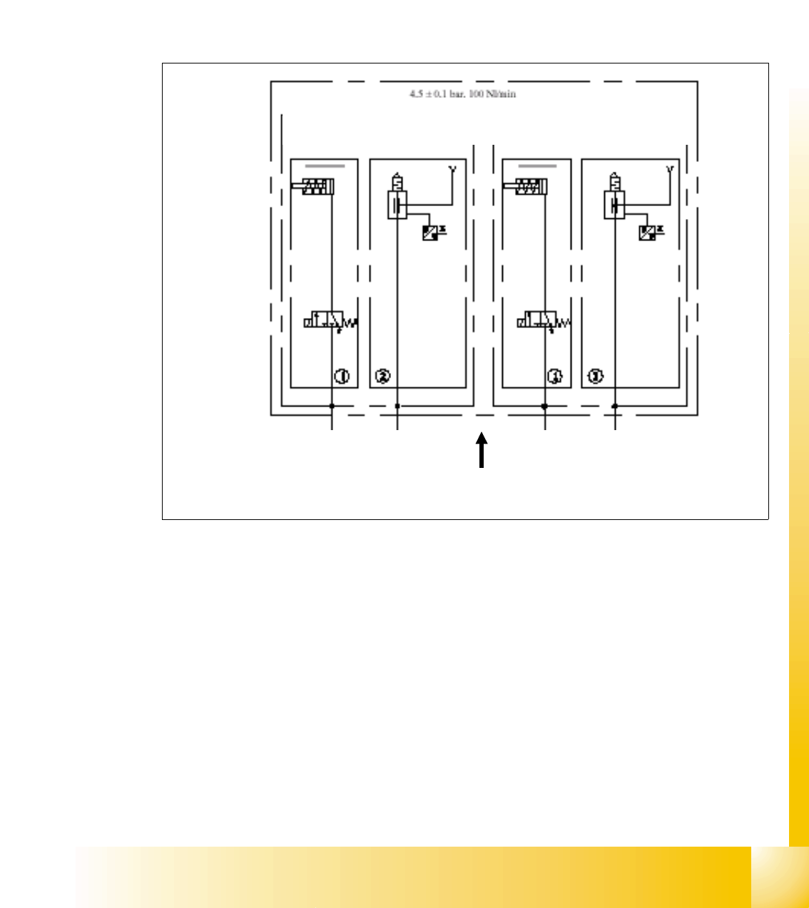
4.3.8 Pneumatic Supply Twin Head:
The 4.8 bar air supply is also used for following basic application on the Twin head:
– vacuum
– air kiss
– retract spring for z-axis
– cooling X-axis motor
4
Fig. 4.3 - 17 pneumatic distribution Twin head
Legend:
1. retracting cylinder for Z-axisTWIN-head segment
2. vacuum generator TWIN-head segment1
3. retracting cylinder for Z-axis twin head segment 2
4. vacuum generator TWIN-head segment 2
5. cylinder with spring for retracting Z-axis in fail mode
6. valve for Z-axis retract process in fail mode (controlled by power fail)
3 4
1 2
4.6 +0.1 bar
6
6
5
5
1 - 46
Student Guide SIPLACE X
4 Services to the machine Edition 09/2005
46
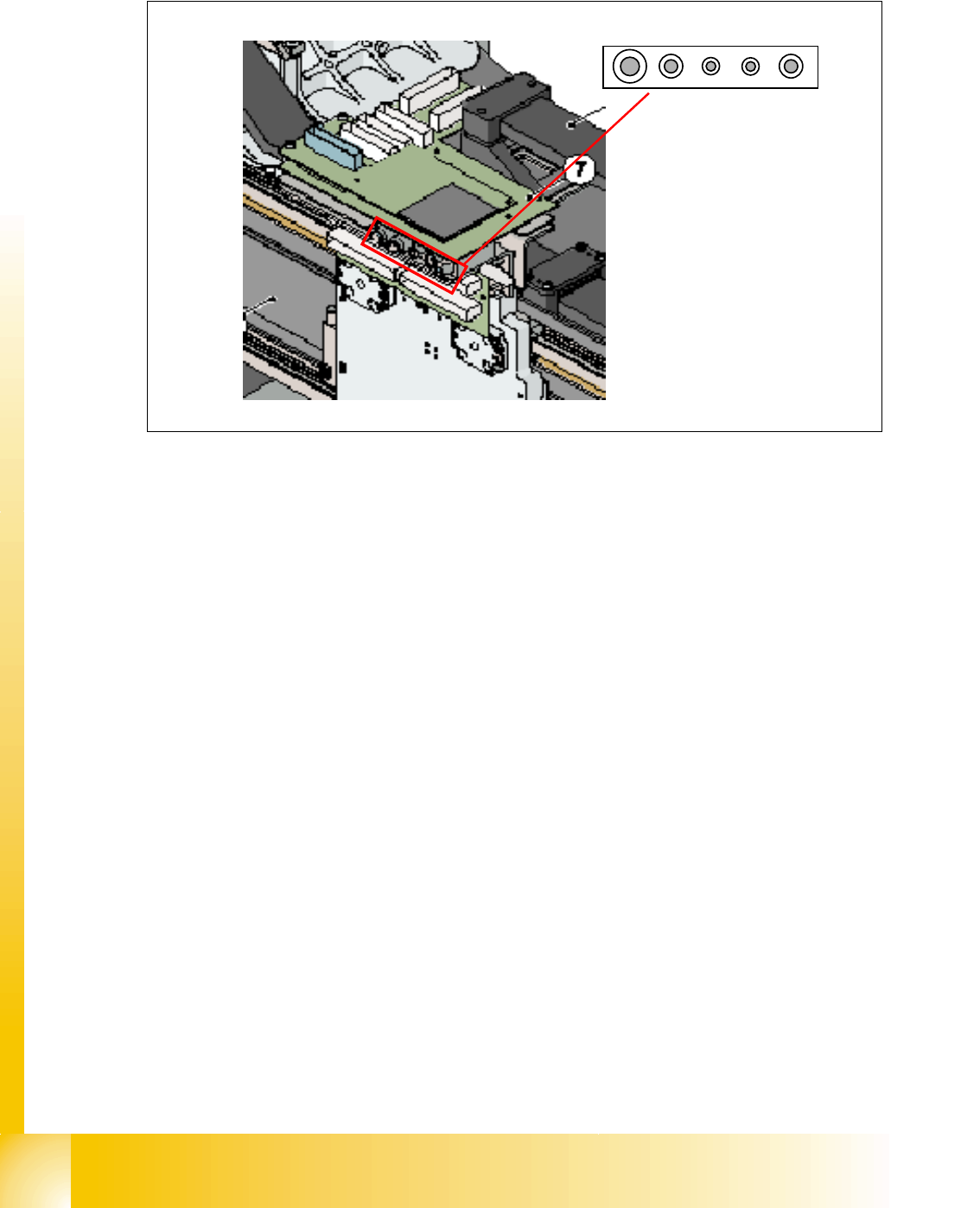
4.3.8.1 Air distribution Twin Head
4
Fig. 4.3 - 18 air distribution TWIN-head
4
Legend
:
1. sealed
2. air supply TWIN-head segment 1 vacuum-air kiss generator
3. air supply TWIN-head segment 1 Z-axis retract unit
4. air supply TWIN-head segment 2 vacuum-air kiss generator
5. air supply TWIN-head segment 2 Z-axis retract unit
4
4
4
4
4
4
4
4
4
4
1 2 3 4 5
1 - 47
Student Guide SIPLACE X
Edition 09/2005 4 Services to the machine
47
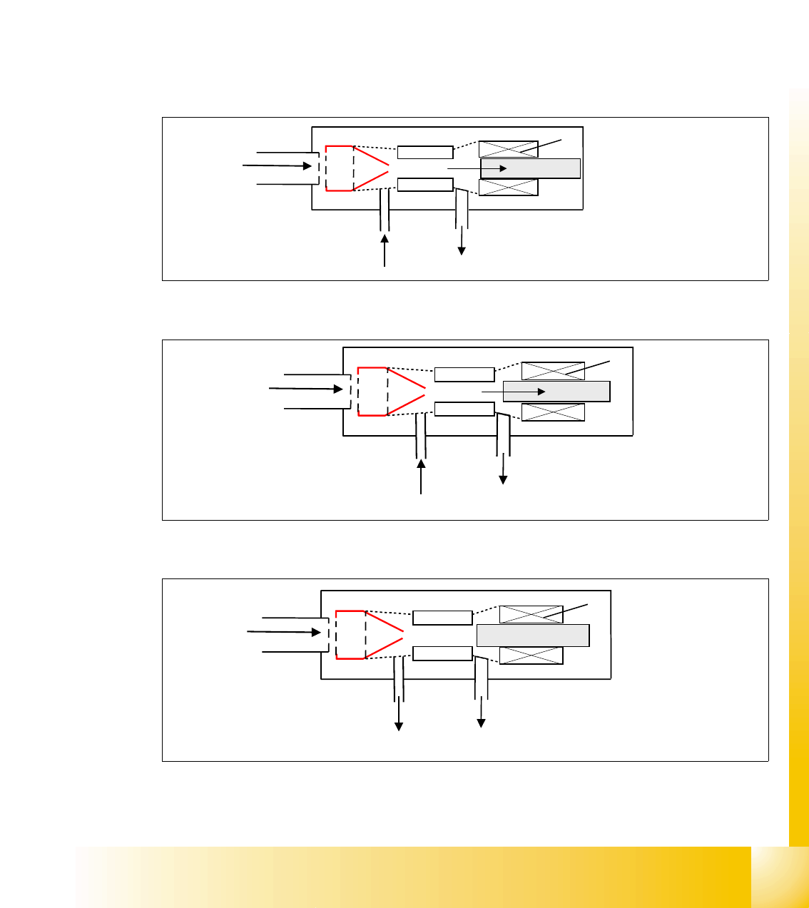
4.3.8.2 Vacuum and air kiss at Twin Head
The vacuum generation and the vacuum regulation at the Twin head is a fully sophisticated
new process. The vacuum and air kiss is not anymore seperated, as known from former vac-
uum systems we used. Furthermore, 1 venturi system is used for vacuum and air kiss by con-
trolling it through an adjustable piston. Depending on the position of this piston 3 different
states are to regulate.
4
state 1: normal vacuum generation (max. vacuum) 4
state 2: regulated and controlled vacuum 4
state 3: no vacuum, air kiss in case 4
Fig. 4.3 - 19 max. vacuum
Fig. 4.3 - 20 regulated vacuum
Fig. 4.3 - 21 air kiss
Input compressed
air 4.6 bar
1
2
3
4
air exhaust (open)
max. vacuum
Legend:
1. venturi nozzle
2. plunger for vacuum / airkiss
generation
3. vacuum / airkiss
4. exhaust pipe
Input compressed
air 4.6 bar
1
2
3
4
air exhaust (open)
medium vacuum
Input compressed
air 4.6 bar
1
2
3
4
air kiss air exhaust (blocked)air kiss