SiplaceX4_en.pdf - 第194页
1 - 48 S tudent Guide SIPLACE X 4 Services to the machine Edition 09/2005 48 4.3.8.3 Z -axis safety process Another use of 4.6 bar compre ssed air is the Z-axis safety process. As long the machine is in a normal mode, th…
1 - 47
Student Guide SIPLACE X
Edition 09/2005 4 Services to the machine
47
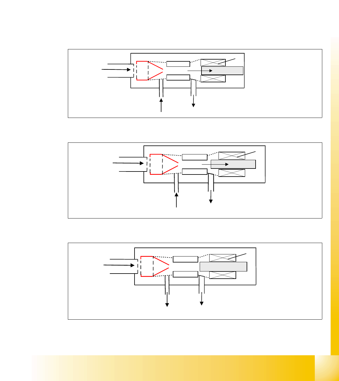
4.3.8.2 Vacuum and air kiss at Twin Head
The vacuum generation and the vacuum regulation at the Twin head is a fully sophisticated
new process. The vacuum and air kiss is not anymore seperated, as known from former vac-
uum systems we used. Furthermore, 1 venturi system is used for vacuum and air kiss by con-
trolling it through an adjustable piston. Depending on the position of this piston 3 different
states are to regulate.
4
state 1: normal vacuum generation (max. vacuum) 4
state 2: regulated and controlled vacuum 4
state 3: no vacuum, air kiss in case 4
Fig. 4.3 - 19 max. vacuum
Fig. 4.3 - 20 regulated vacuum
Fig. 4.3 - 21 air kiss
Input compressed
air 4.6 bar
1
2
3
4
air exhaust (open)
max. vacuum
Legend:
1. venturi nozzle
2. plunger for vacuum / airkiss
generation
3. vacuum / airkiss
4. exhaust pipe
Input compressed
air 4.6 bar
1
2
3
4
air exhaust (open)
medium vacuum
Input compressed
air 4.6 bar
1
2
3
4
air kiss air exhaust (blocked)air kiss
1 - 48
Student Guide SIPLACE X
4 Services to the machine Edition 09/2005
48
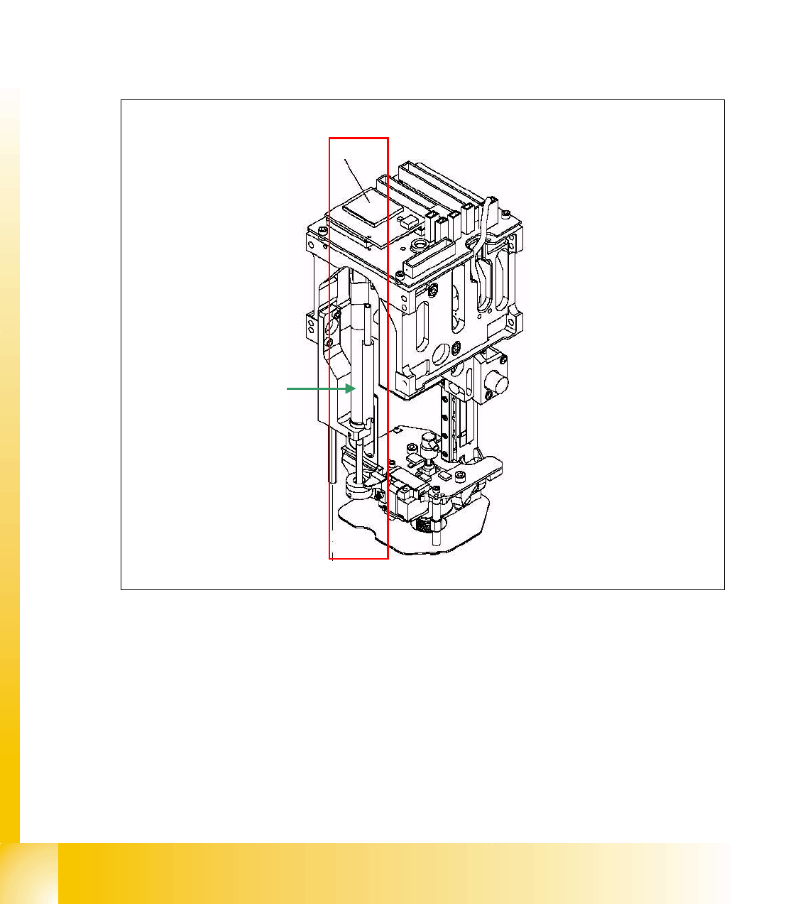
4.3.8.3 Z-axis safety process
Another use of 4.6 bar compressed air is the Z-axis safety process. As long the machine is in a
normal mode, the Z-axis keeps position on zero digits. In case, power drops down, it must be se-
cured, the Z-axis does not remain or fall down in any down position.
This is realized by a spring, which retracts the z-axis to top position by extending. As long as there
is no fault event, the spring is pressed by a 4.6 bar compressed air pressure. In a fault event, like
power drop, the power fail mode is activated, which powers the z-axis for about 200 ms seconds
with the aid of a capacitor, located in the main power supply. This secures the Z-axis moves up
with power and with additional help through retract spring.
Fig. 4.3 - 22 Z-axis retract unit
retract device

Student Guide SIPLACE X
Edition 09/2005 Contents
1
Chapter
Table of contents
5 Gantry. . . . . . . . . . . . . . . . . . . . . . . . . . . . . . . . . . . . . . . . . . . . . . . . . . . . . . . . . . . . . 3
5.1 Overview Gantry . . . . . . . . . . . . . . . . . . . . . . . . . . . . . . . . . . . . . . . . . . . . . . . . . . . . . . . . . . . . . . . . 3
5.1.1 Mechanical structur of the X- and Y- axes. . . . . . . . . . . . . . . . . . . . . . . . . . . . . . . . . . 5
5.1.2 Pneumatic connectors on the gantry . . . . . . . . . . . . . . . . . . . . . . . . . . . . . . . . . . . . . . 6
5.2 Reference run Gantry . . . . . . . . . . . . . . . . . . . . . . . . . . . . . . . . . . . . . . . . . . . . . . . . . . . . . . . . . . . . 7
5.2.1 Sequence reference run at X- and Y-axis . . . . . . . . . . . . . . . . . . . . . . . . . . . . . . . . . . 7
5.2.2 X and Y commutation position search . . . . . . . . . . . . . . . . . . . . . . . . . . . . . . . . . . . . . 8
5.2.3 Reference run of X- and Y- axes . . . . . . . . . . . . . . . . . . . . . . . . . . . . . . . . . . . . . . . . . 8
5.3 Adjustments . . . . . . . . . . . . . . . . . . . . . . . . . . . . . . . . . . . . . . . . . . . . . . . . . . . . . . . . . . . . . . . . . . . . 9
5.3.1 Travel range and velocity monitoring X- and Y- Axes on the X2. . . . . . . . . . . . . . . . . 9
5.3.2 Travel range and velocity monitoring X- and Y- Axes on the X3. . . . . . . . . . . . . . . . 10
5.3.2.1 Adjustments BERO‘s . . . . . . . . . . . . . . . . . . . . . . . . . . . . . . . . . . . . . . . . . . . . . 11
5.3.2.2 Description of the BERO‘s on the Y-Axis . . . . . . . . . . . . . . . . . . . . . . . . . . . . . . 11
5.3.3 Description of the PCB boards on the Gantry . . . . . . . . . . . . . . . . . . . . . . . . . . . . . . 12
5.3.3.1 Head interface C500 . . . . . . . . . . . . . . . . . . . . . . . . . . . . . . . . . . . . . . . . . . . . . 12
5.3.3.2 Vision board (digital). . . . . . . . . . . . . . . . . . . . . . . . . . . . . . . . . . . . . . . . . . . . . . 14
5.3.3.3 CAN Processorboard 16 Bit . . . . . . . . . . . . . . . . . . . . . . . . . . . . . . . . . . . . . . . . 15
5.3.3.4 Check the DIP Switches. . . . . . . . . . . . . . . . . . . . . . . . . . . . . . . . . . . . . . . . . . . 16
5.3.4 Anti crash board . . . . . . . . . . . . . . . . . . . . . . . . . . . . . . . . . . . . . . . . . . . . . . . . . . . . 18
5.3.5 Mechanical adjustment the incremental encoder . . . . . . . . . . . . . . . . . . . . . . . . . . . 19
5.4 Track signals and Zero pulse . . . . . . . . . . . . . . . . . . . . . . . . . . . . . . . . . . . . . . . . . . . . . . . . . . . . . 21
5.4.1 Check the zero pulse signal . . . . . . . . . . . . . . . . . . . . . . . . . . . . . . . . . . . . . . . . . . . 21
5.4.1.1 Measurement the analog zero pulse signal . . . . . . . . . . . . . . . . . . . . . . . . . . . . 21
5.4.1.2 Measurement the digital zero pulse signal . . . . . . . . . . . . . . . . . . . . . . . . . . . . . 23
5.4.2 Check the track signals . . . . . . . . . . . . . . . . . . . . . . . . . . . . . . . . . . . . . . . . . . . . . . . 25
5.4.2.1 Analog track signals . . . . . . . . . . . . . . . . . . . . . . . . . . . . . . . . . . . . . . . . . . . . . . 25
5.4.2.2 Digital Track signals . . . . . . . . . . . . . . . . . . . . . . . . . . . . . . . . . . . . . . . . . . . . . . 26
5.5 Axis control . . . . . . . . . . . . . . . . . . . . . . . . . . . . . . . . . . . . . . . . . . . . . . . . . . . . . . . . . . . . . . . . . . . 27
5.5.1 Parts for the axis control . . . . . . . . . . . . . . . . . . . . . . . . . . . . . . . . . . . . . . . . . . . . . . 27
5.5.2 Check dynamic X-axis . . . . . . . . . . . . . . . . . . . . . . . . . . . . . . . . . . . . . . . . . . . . . . . . 28
5.5.2.1 Test setup with Axis testbox. . . . . . . . . . . . . . . . . . . . . . . . . . . . . . . . . . . . . . . . 28
5.5.2.2 Test setup with SAT-Box . . . . . . . . . . . . . . . . . . . . . . . . . . . . . . . . . . . . . . . . . . 29
5.5.2.3 Travel profile X-axis C&P 20, C&P 6/12 head and Twin head in comparison . . 30
5.5.2.4 Positioning time tables X-Axis depended on the head types . . . . . . . . . . . . . . . 31