SiplaceX4_en.pdf - 第199页
1 - 5 S tudent Guide SIPLACE X Edition 09/2005 5 Gantry 5 5.1.1 Mechanical structur of the X- and Y - axes Please Note: X- and Y - Axes have the same basic mechanical parts. Fig. 5.1 - 3 Mechanical structure "Gantry…
1 - 4
Student Guide SIPLACE X
5 Gantry Edition 09/2005
4
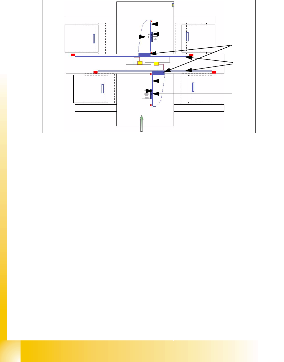
Fig. 5.1 - 2 Main parts at the "Gantries" e.g. X2
Legend
(1) Secondary part X-axis (Magnet) (2) Primary part X-axis (Linear motor)
(3) Primary part Y-axis (Linear motor) (4) Secondary part Y-Axis (Magnet)
(5) Secondary part X-axis (Magnet) (6) Primary part X-axis (Linear motor)
(7) PCB camera under the X-axis (8) PCB camera mounted under the gantry
1
2
3
4
5
6
7
8
1 - 5
Student Guide SIPLACE X
Edition 09/2005 5 Gantry
5
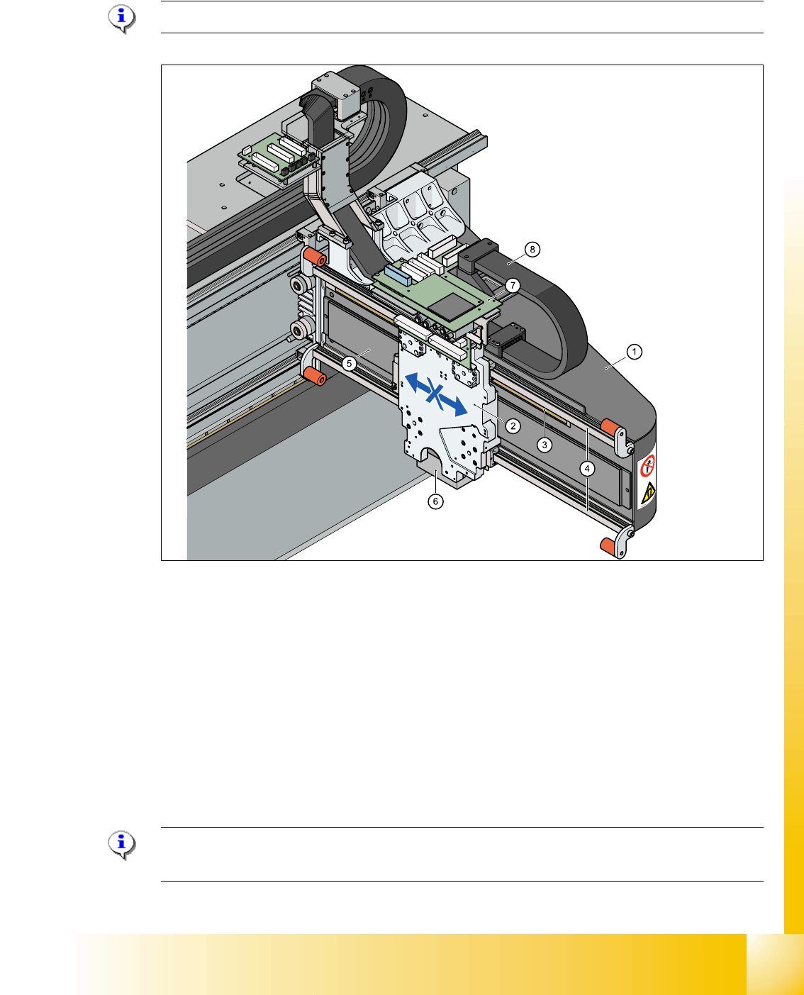
5.1.1 Mechanical structur of the X- and Y- axes
Please Note: X- and Y- Axes have the same basic mechanical parts.
Fig. 5.1 - 3 Mechanical structure "Gantry"
Legend
Please Note: The temperature sensor compensates according the temperature of the head
mounting plate the offset between PCB camera and nozzle to ensure the highest accuracy.
(1) X-axis (carbon fiber composite material) (Three
kinds of gantry possible, CFK 02 (HF), CFK
04(HF,X) and CFK 06 (X) configurable)
(2) Head mounting plate with integreted tempera-
tur sensor
(3) Incremental scale X-Axis (4) Linear guidance (above/below the magnet)
(5) Secondary part X-axis (Magnet) (6) PCB-camera below the X-axis
(7) Boards (Head interface with Vision board below -
vertical- is the Adapter board)
(8) X- trailling cable
1 - 6
Student Guide SIPLACE X
5 Gantry Edition 09/2005
6
Description: 5
The head mounting plate with the C&P head or TWIN-head is moved via the linear guidance which
are mounted over the secondary part of the linear motor and under the secondary part of the linear
motor in X direction. The Y- axis moves the entire X-axis with the C&P or TWIN-head.
For X and Y position recognition we use incremental metal scales. They are positioned over the
secondary part of the X - Linear motor and under the secondary part of the Y- Linear motor. A cor-
responding incremental encoder reads the increments from the metal scales and generates track
signals as a result. The encoder transmits the track signals to the axis control card, which uses
the track signals to determine axis position and to control the motor.
Left and right of every incremental scale are mounted the metal actuators for the BERO´s. The
BERO‘s on the X- and Y- axes are required for the reference run, the velocity check and the
hardware limit switch.
Additionally each axis has a mechanical end stop (elastomer bumper).
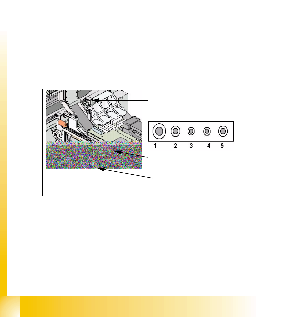
5.1.2 Pneumatic connectors on the gantry
Fig. 5.1 - 4 Pneumatic connectors on the gantry
Pneumatic connectors Legend
– Cooling the Y- axes occurs via a motor which generate compressed air it is mounted in the
pneumatic unit.
– The X axes are cooled from the C&P head or Twin head with exhaust of the vacuum system.
(1) Holding circuit C&P6/12/20 head (2) C&P6/12 head pick up circuit an air kiss
(2) Twin head Segment 1 vacuum generator (3) Twin head Segment 1 retract unit
(4) Twin head Segment 2 / C&P20 retract unit (5) Twin head Segment 2 / C&P20 Vacuum
generator
Pneumatic connector for cooling the Y-Linear
motor
Pneumatic connectors under the Head interface.
Pneumatic connector for cooling the X-Linear
motor