SiplaceX4_en.pdf - 第203页
1 - 9 S tudent Guide SIPLACE X Edition 09/2005 5 Gantry 9 5.3 Adjustment s 5.3.1 T ravel range and velocity m onitoring X- and Y - Axes on the X2 The travel range of the X- and Y -axes will be dete rmined automatically w…
1 - 8
Student Guide SIPLACE X
5 Gantry Edition 09/2005
8
5.2.2 X and Y commutation position search
A commutation position search for the 3 phases AC-drives on the gantry starts right after the
head axis reference run is succesfully finished.
A 3 phase motor move on and on when the current is switched from 1 phase to the next one, at
the correct time and in the correct sequence.
First one of the phases is connect to the power supply. With the incremental encoder the move-
ment is measured. Than the current is switched to the next phase and this movement is measured
too. The machine repeat this to control the measurement values.
This axis mode of commutation position search for the digital axis controller seams like a ”uncon-
trolled” shaking.
5.2.3 Reference run of X- and Y- axes
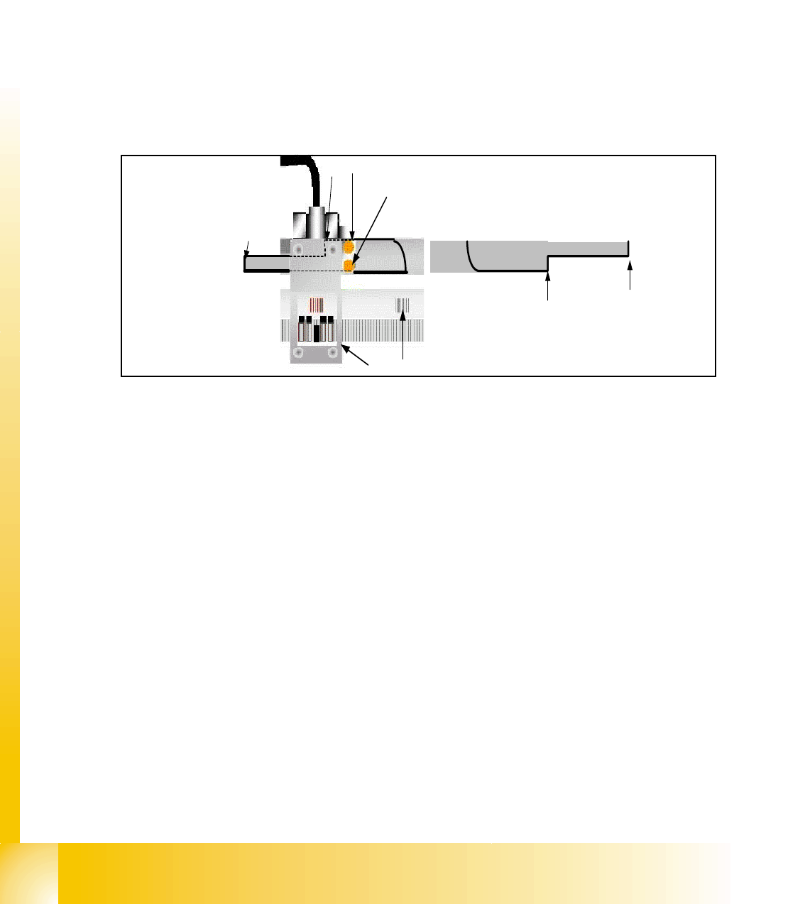
Fig. 5.2 - 2 Metal plate for switching position the BERO
1. Metal plate integrated into the machine frame
2. & 2b Switching position for HW-limit switch (Travel range)
3. Switching position for reference BERO / 3b start speed controled mode (near axis endstop)
4. BERO for limit switch (left side)
5. BERO for reference
6. First zero puls on the incremental scale
7. Incremental encoder
– The reference run is done with a defined travel range BERO and the incremental encoder.
– First the gantry axes move to the reference Bero (
4).
– If the switching position(
3) is detected the direction of movement is reversed and the Zero
pulse signal (
6) search starts.
– When the Zero pulse is detected the zero point correction is loaded to the axis controller. Ref-
erence run gantry axes is completed.
– After the whole refernce run of the axes starts the initialization of the Transport system
– All transport motors except Input conveyor and conveyors their light barrier sensor are covered
by a PCB will be activated.
1
2b
3b
6
5
4
7
3
2
1 - 9
Student Guide SIPLACE X
Edition 09/2005 5 Gantry
9
5.3 Adjustments
5.3.1 Travel range and velocity monitoring X- and Y- Axes on the X2
The travel range of the X- and Y-axes will be determined automatically with Sitest program. That
means, during calibration of travel range the axis run as far as possible into its minimum and/or
maximum position. The axis position is taken when the limit-BERO´s switch. Corresponding the
description (see below) a safety space infront of the hardware limit switch is calculated for SW-
travel limit.
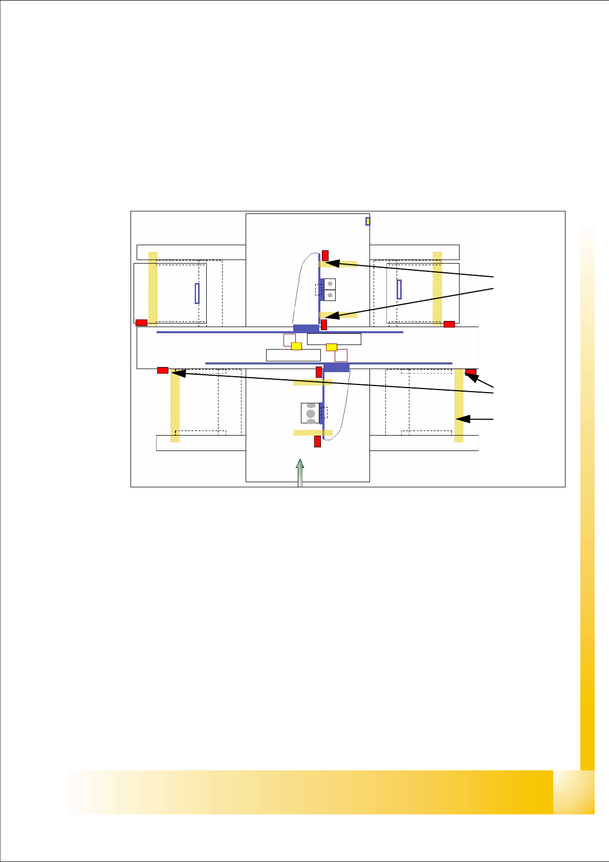
Fig. 5.3 - 1 Travel range X- and Y-axes e.g. X2
Legend
a The end of the travel range of the X-axis be + or - 0,5 mm before the hardware limit switch
(software limit switch).
For velocity check, a range of
45 mm before the hardware limit switch was determined. This
way is sufficient, if the X- axis move with to high velocity into this field. It will be stop by the anti
crash board immediately.
s The end of the travel range of the Y-axis be + or - 1,5 mm before the hardware limit switch
(software limit switch).
For velocity check, a range of
65 mm before the hardware limit switch was determined. This
way is sufficient, if the Y- axis move with to high velocity into this field. It will be stop by the anti
crash board immediately.
(1) Travel range (min./max.pos.) X-axis (2) Travel range (min./max.pos.)Y-axis
(3) those areas show the range with reduced speed near the bumpers
1
2
3
1 - 10
Student Guide SIPLACE X
5 Gantry Edition 09/2005
10
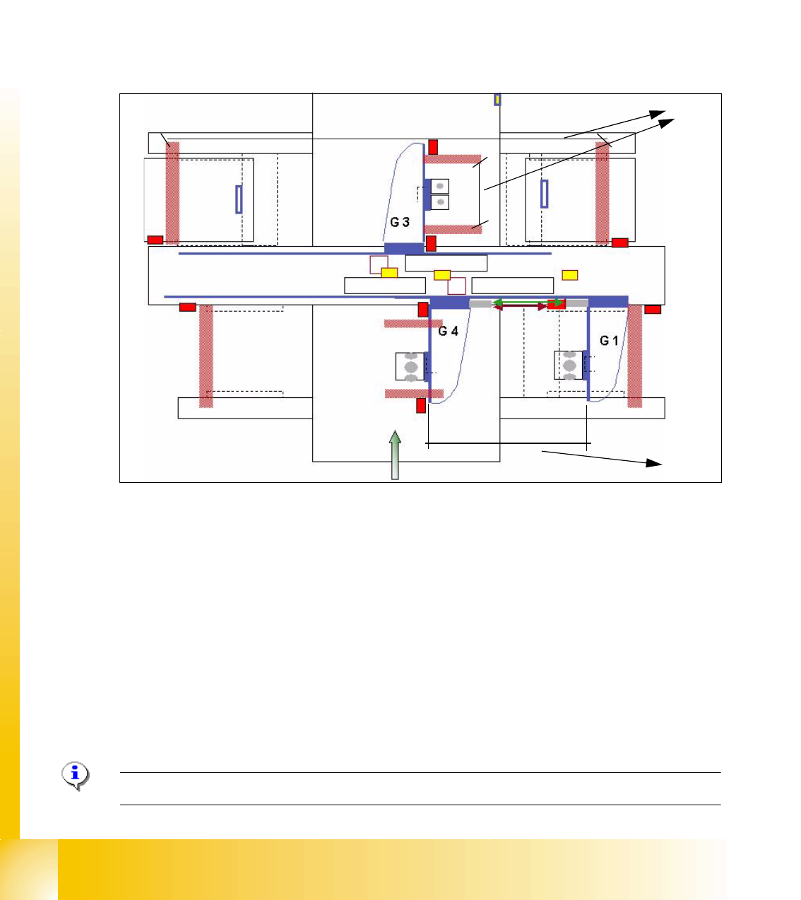
5.3.2 Travel range and velocity monitoring X- and Y- Axes on the X3
The travel range of the X- and Y-axes will be determined automatically with Sitest program. That
means, during calibration of travel range the gantry 3 went as far as possible into its minimum and
maximum position. Corresponding the description (see travel range HF) a safety space in front of
the hardware limit switch is calculated. At HF 3 machine we have two gantries in the placement
area 1 so the Y-axis of the gantry 1 went to the minimum position and the Y-axis of gantry 4 went
to the maximum position. After that we calculate the minimum position for gantry 4 according min.
pos. of gantry 1. The maximum position for gantry 1 we calculate on the result of maximum pos.
of gantry 4.(see below)
Fig. 5.3 - 2 Travel range X- and Y-axes X3 machine
(1) The calculation of the travel range for the X-axes on gantries 1 / 3 / 4 and Y-axes from the
gantry 3 is the same as the HF machine.
(2) The travel range for the y-axes on the gantries 1 and 4 are calculated partly. That means, the
Y-axis of Gantry 1 moves into the minimum position and the Y-axis of gantry 4 moves into the
maximum position. The calculation is:
Maximum position gantry 1 = Maximum position gantry 4 - 480mm (gantry width) - 20mm
safety space. (On the X4 is the travel range according to the gantry 2)
Minimum position gantry 4 = Minimum position gantry 1 + 480mm (gantry width) + 20mm
safety space. (On the X4 is the travel range according to the gantry 3)
(3) Safety space approx. 20mm
Please Note: For adjust the Anti Crash board see 5.3.4.
1
2
3