SiplaceX4_en.pdf - 第210页
1 - 16 S tudent Guide SIPLACE X 5 Gantry Edition 09/2005 16 5.3.3.4 Check the DIP Switches DIP Switches on the head interface 5 Legend for DIP Switches Attention : With Head Modularity p ay attention: That termin at ing …
1 - 15
Student Guide SIPLACE X
Edition 09/2005 5 Gantry
15
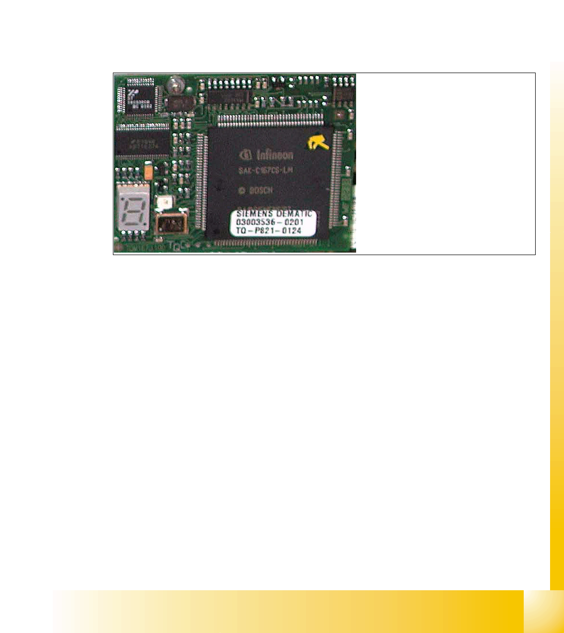
5.3.3.3 CAN Processorboard 16 Bit
The 16 BIT CAN Processor are use for different functions of the following units: (see chapter com-
munication and control too)
– Visionboard, communication and control via the CAN Bus to the vision computer.
– Head processor board (C500), if Twin head installed, control the vacuumgenerator.
– Head processor board (C500), if C&P head installed, control the head sequence.
– Visionboard for the stationary IC (FC) - Camera (sector 2 and 4), communication and con-
trol via the CAN Bus to the Vision computer.
Fig. 5.3 - 6 16 Bit Processor (TQM Module)
Description 7 Segment display ( Standard mode " . " flashed):
– After switch ON the machine appears " 0 " on the display
– Display " b " Bios is started.
– Display flash alternately "b" and " . " --> none Application available or can not started.
– Display " -I " und " I- " Application is loaded and now starts.
– The " . " on the display flashed.
(1) 7 Segment display
(2) LED red at the bei manual RESET
on the Processors
(3) 16 Bit Processor
2
3
1
1 - 16
Student Guide SIPLACE X
5 Gantry Edition 09/2005
16
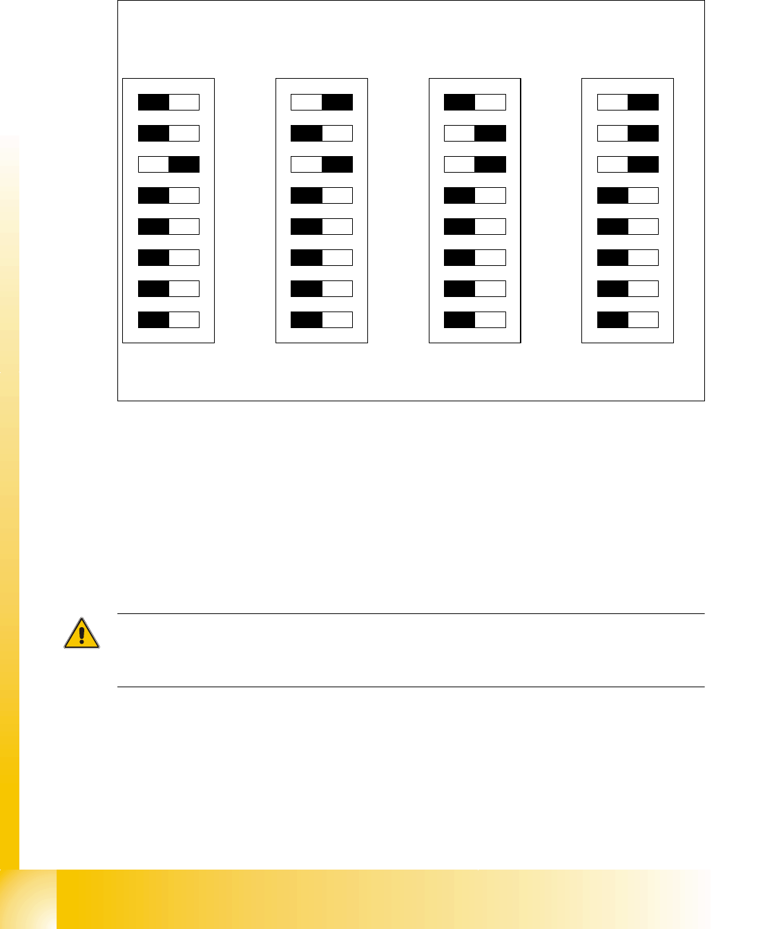
5.3.3.4 Check the DIP Switches
DIP Switches on the head interface 5
Legend for DIP Switches
Attention:
With Head Modularity pay attention: That terminating CAN resistor is set correctly. That means, at
the C&P heads switch CAN-Terminator ON and at the TWIN-head switch it OFF.(DIP Switch 3)
(1) P0 - Gantry address switch 1 (2) P1 - Gantry address switch 2
(3) CAN R - CAN terminator
(At TWIN-option always OFF)
(4) Boot - CAN Processor 16 Bit not mounted
(5) Reset - CAN Processor 16 Bit not mounted (6) C0 - CAN Address switch
(7) C1 - CAN Address switch (8) WPE - Write protect enable at the moment
OFF
DIP Switch
ON
78123456
ON
78123456
ON
78123456
ON
78123456
Gantry 1
Gantry 2
Gantry 3 Gantry 4
C&P Head
C&P Head
C&P Head
C&P Head
1 - 17
Student Guide SIPLACE X
Edition 09/2005 5 Gantry
17
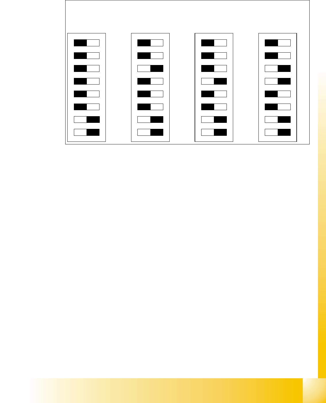
DIP Switches on the vision board 5
Legend
(1) Boot - CAN Processor 16 Bit at Sub board (2) Reset - CAN Processor 16 Bit at Sub board
(3) P0 - Gantry address switch 1 (4) P1 - Gantry address switch 2
(5) WPE - Write protect enable at the moment
OFF
(6) CAN R - CAN terminator
(7) Test 1 - CAN 1MBit/s ON (8) Test 0 - CAN group ON
DIP Switch
ON
78123456
ON
78123456
ON
78123456
ON
78123456
Gantry 1
Gantry 2
Gantry 3 Gantry 4