SiplaceX4_en.pdf - 第215页
1 - 21 S tudent Guide SIPLACE X Edition 09/2005 5 Gantry 21 5.4 T rack signals and Zero pulse 5.4.1 Check the zero pulse signal The zero pulse on the incremen tal scale must be reco gnize from the incremen tal encoder se…

1 - 21
Student Guide SIPLACE X
Edition 09/2005 5 Gantry
21
5.4 Track signals and Zero pulse
5.4.1 Check the zero pulse signal
The zero pulse on the incremental scale must be recognize from the incremental encoder secure
and perfectly. To check the zero pulse you can check the analog or digital zero pulse.
If the zero pulse is not recognize correctly, the axis will reference to a spurious peak. Placement
offsets will be the result.
On the incremental measurement you can‘t make any electrical adjustments.
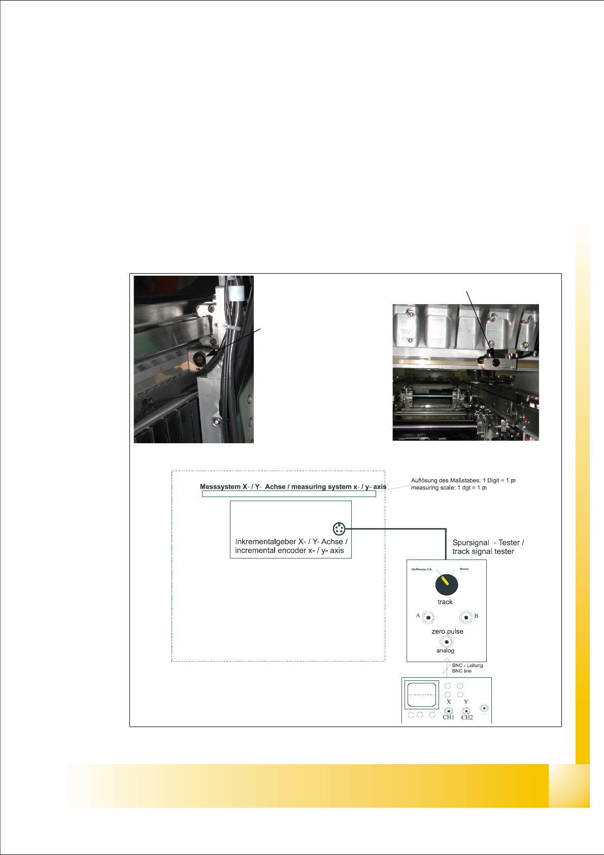
5.4.1.1 Measurement the analog zero pulse signal
Fig. 5.4 - 1 Test setup to check the analog zero pulse and track signals
Incremental encoder
X - Axis
Incremental encoder X - Axis
1 - 22
Student Guide SIPLACE X
5 Gantry Edition 09/2005
22
Test procedure 5
➠ Connect the track signal tester on the incremental encoder.
➠ Switch "ON" the main switch
➠ Connect the oszilloscope on the track signal tester.
➠ Set the switch to "Oszilloscope calibrate" on the track signal tester.
➠ Positioning the signal to the middle from the upper half of the display. (see picture below)
Fig. 5.4 - 2 Initinal start point to measure the zero pulse.
Please Note:
Check the first zero pulse which you need for the reference run on the incremental scale.
➠ Move by hand the gantry over the first zero pulse.
➠ It should appear the following picture on the oscilloscope.
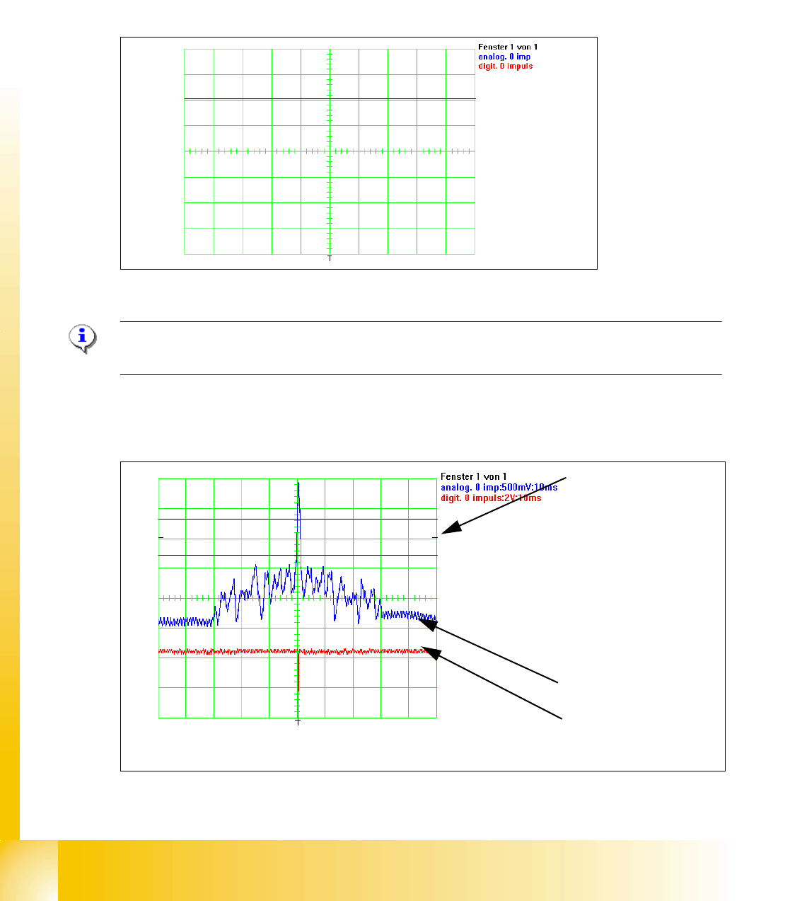
Fig. 5.4 - 3 Adjustment of the incremental encoder correct
Initial start position
1. In the Tolerance
space of - 0,3 V you
don‘t have an inter-
ference pulse.
2. The analog zero
pulse have to over
the tolerance space
more then 0,3V
analog zero pulse
digital zero pulse
1
2