SiplaceX4_en.pdf - 第217页
1 - 23 S tudent Guide SIPLACE X Edition 09/2005 5 Gantry 23 Fig. 5.4 - 4 Incremental encoder wr ong adjusted or poluted zero pulse Legend 5.4.1.2 Measurement the digit al zero pulse signal Please Note: Also for checking …
1 - 22
Student Guide SIPLACE X
5 Gantry Edition 09/2005
22
Test procedure 5
➠ Connect the track signal tester on the incremental encoder.
➠ Switch "ON" the main switch
➠ Connect the oszilloscope on the track signal tester.
➠ Set the switch to "Oszilloscope calibrate" on the track signal tester.
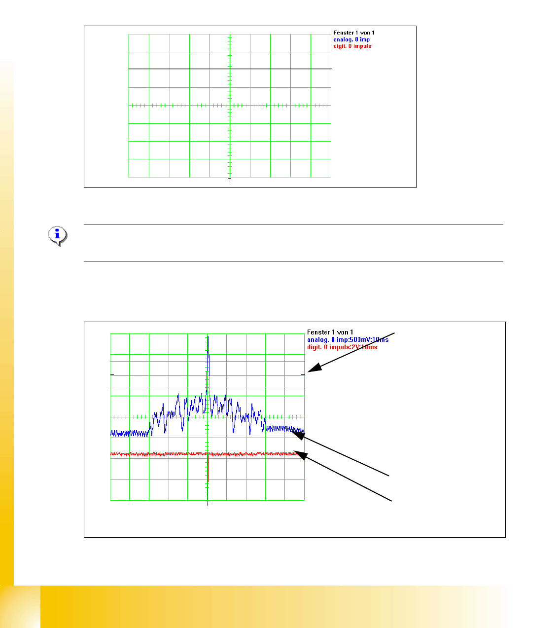
➠ Positioning the signal to the middle from the upper half of the display. (see picture below)
Fig. 5.4 - 2 Initinal start point to measure the zero pulse.
Please Note:
Check the first zero pulse which you need for the reference run on the incremental scale.
➠ Move by hand the gantry over the first zero pulse.
➠ It should appear the following picture on the oscilloscope.
Fig. 5.4 - 3 Adjustment of the incremental encoder correct
Initial start position
1. In the Tolerance
space of - 0,3 V you
don‘t have an inter-
ference pulse.
2. The analog zero
pulse have to over
the tolerance space
more then 0,3V
analog zero pulse
digital zero pulse
1
2
1 - 23
Student Guide SIPLACE X
Edition 09/2005 5 Gantry
23
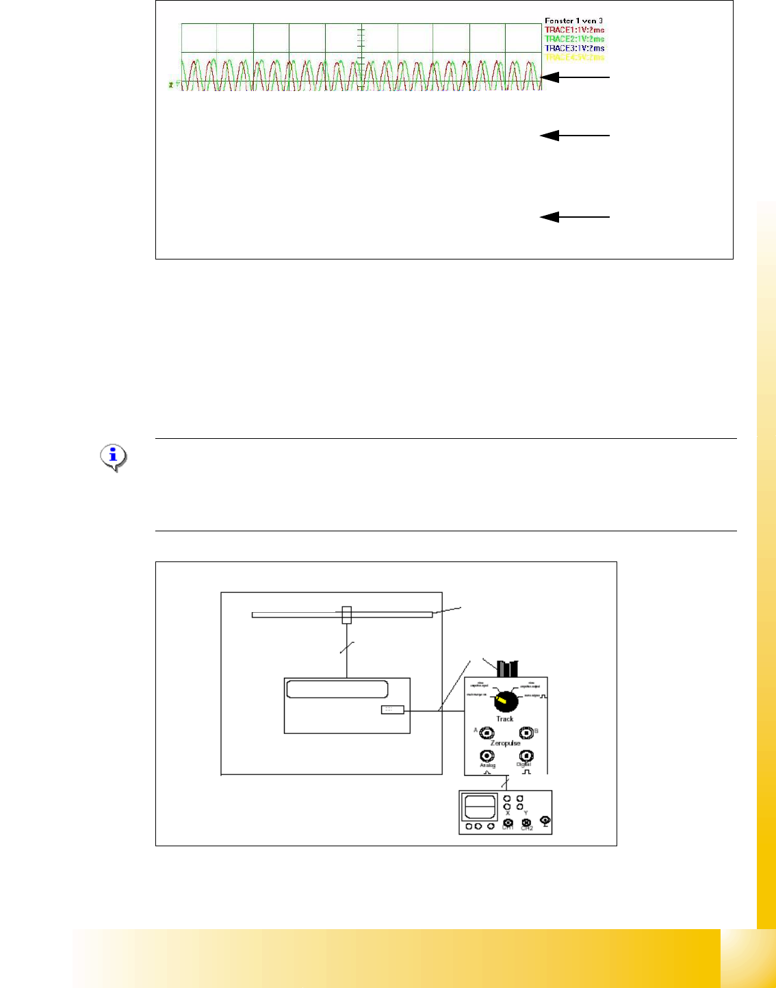
Fig. 5.4 - 4 Incremental encoder wrong adjusted or poluted zero pulse
Legend
5.4.1.2 Measurement the digital zero pulse signal
Please Note: Also for checking the zero pulse you can use the BNC connector from the axis test
box (inverse signal).
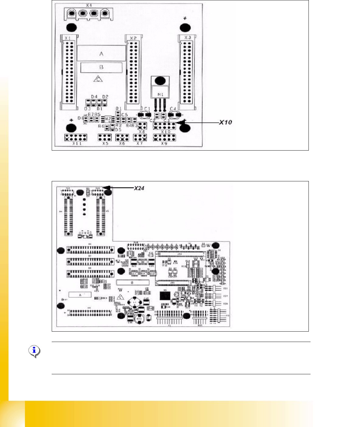
On the connectors X10 and X24 on gantry -and headinterface can you check the digital Signals.
(Y-Axis, more time to dismounting the covers)
Fig. 5.4 - 5 Test setup to check the digital zero pulse and track signals
(1) analog track signal A and B (2) analog zero pulse
(3) digital zero pulses
1
2
3
Test setup for digital zero pulse and track signals
Measurment system X/Y Axis
Track A/B/N
Resolution incremental scale
1 Digit= 1µm
Track signal
tester
BNC-cable
Siplace HF
Board
Test connector
Ribbon cable
1 - 24
Student Guide SIPLACE X
5 Gantry Edition 09/2005
24
X10 on the Gantry Interface Y-axis 5
X24 on the head interface X-axis 5
Please Note:
The measurement procedure for measurment the digital zero pulse is the same as the analog zero
pulse.
Connector:
Pin 1 Ground
Pin 2 Track A
Pin 3 Track A\
A\ mean inverted A
Pin 4 Ground
Pin 5 Track B
Pin 6 Track B\
Pin 7 +5V
Pin 8 Track N
Pin 9 Track N\
Pin 10 Key
Connector:
Pin 1 Ground
Pin 2 Track A
Pin 3 Track A\
Pin 4 Ground
Pin 5 Track B
Pin 6 Track B\
Pin 7 +5V
Pin 8 Track N
Pin 9 Track N\
Pin 10 Key