SiplaceX4_en.pdf - 第234页
1 - 6 S tudent Guide SIPLACE X 6 Collect &Place-He ad 6/12 Edition 09/2005 6 6.1.1 T echnical Dat a 6/12 Note Head Modularity The adjustment of the ax es dynamic after exchange the head will be adjust automa tically …
1 - 5
Student Guide SIPLACE X
Edition 09/2005 6 Collect &Place-Head 6/12
5
6 Collect &Place-Head 6/12
6.1 Overview
The Siplace X machine have depending on configuration 20 segment C&P heads,
12- segment C&P heads, 6 segment C&P heads, and/or TWIN-heads ( see chapter 6.5).
6
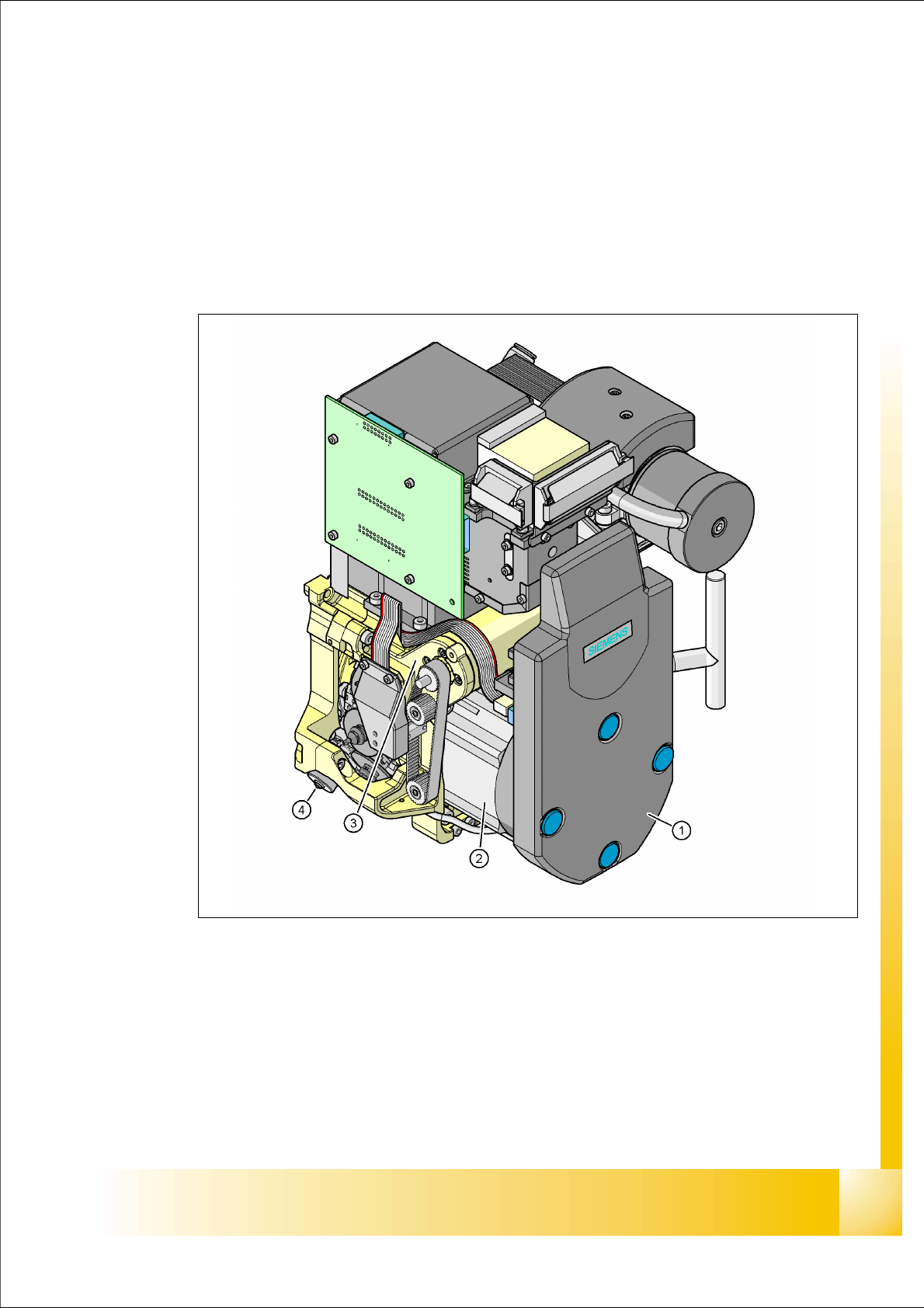
Fig. 6.1 - 1 12-segment Collect&Place head - overview
Legend
(1) Cover intermediate distribution
board, digital (under the cover)
(2) Star drive
(3) Z Drive (4) Stepper motor (Valve drive)
(5) Component Camera C&P, Type 28 (18 x 18) digital or Typ 29 (27 x 27) digital, high resolution
1 - 6
Student Guide SIPLACE X
6 Collect &Place-Head 6/12 Edition 09/2005
6
6.1.1 Technical Data 6/12
Note Head Modularity
The adjustment of the axes dynamic after exchange the head will be adjust automatically from the
axes data base at the configuration setting.
6.1.1.1 Technical Data: 6 Segment / 12 Segment C&P heads
.
6.1.1.2 Camera modularity at the 12segment C&P head for example
Note:
The Standard camera at the 12 C&P head is the sensor typ 28.sst. As DCA -Option can you use
the component camera from the 6 C&P head, sensor typ 29.sst, with the higher resolution.
.
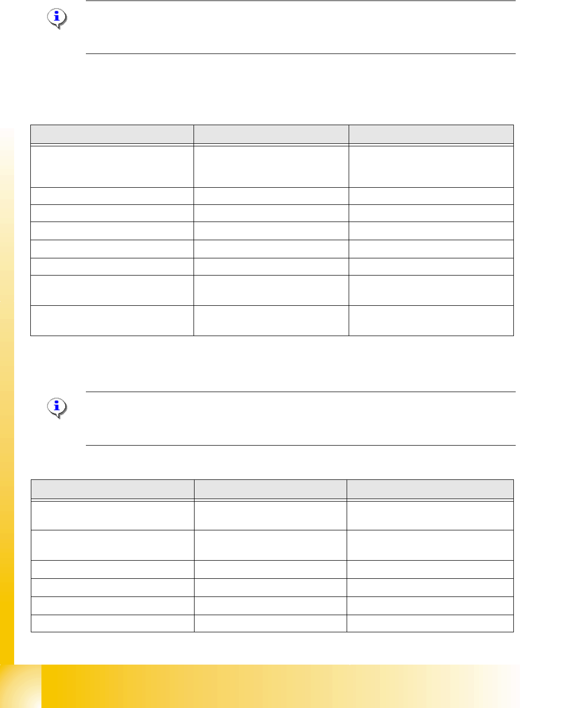
Description 12 segment DLM 2 6 segment DLM 2
Component size
1mm x 0,5mm (0402)/0,5mm x
0,25mm (0201) up to
18,7 mm x 18,7 mm
1,5mm x 0,75 mm (0603) up to
27 mm x 27 mm
Component height 6,0 mm 8,5 mm
Component weight 2,0 g 5,0 g
Placement Accuracy
+/- 60µm at 4 (Sigma) +/- 60µm at 4 (Sigma)
Angle Accuracy
+/- 0,7° at 4 (Sigma) +/- 0,3° at 4 (Sigma)
Placement force 2,4 - 5,0 N 2,4 - 5,0 N
Nozzle types
901, 904, 905; 911-919; 920-
925; 931-937
901, 904, 905; 911-919; 920-925;
931-937 817, 820, 821
Nozzle changer
set up for each magazine or set
up for each garage
set up for each magazine or set up
for each garage
Table 6.1 - 1 Technical data 6 / 12 C&P heads
Description 12 segment standard 12 segment with DCA
Component size
0,5mm x 0,5 mm (0402) up to
18,7 mm x 18,7 mm
0,3mm x 0,3 mm (0201) up to
18,7 mm x 18,7 mm
Component dimension: FlipChip /
Bare Die
1mm x 1 mm up to
15 mm x 15 mm
1mm x 1 mm up to
15 mm x 15 mm
Component height: FlipChip / Bare Die 0,15 mm up to 1 mm
0,15 mm up to 1 mm
Placement accuracy
+/- 60µm at 4 (Sigma) +/- 55µm at 4 (Sigma)
Angle accuracy
+/- 0,4° at 4 (Sigma) +/- 0,4° at 4 (Sigma)
Resolution Component camer 50µm/Pixel 26µm/Pixel
Table 6.1 - 2 Technical data Component camras
1 - 7
Student Guide SIPLACE X
Edition 09/2005 6 Collect &Place-Head 6/12
7
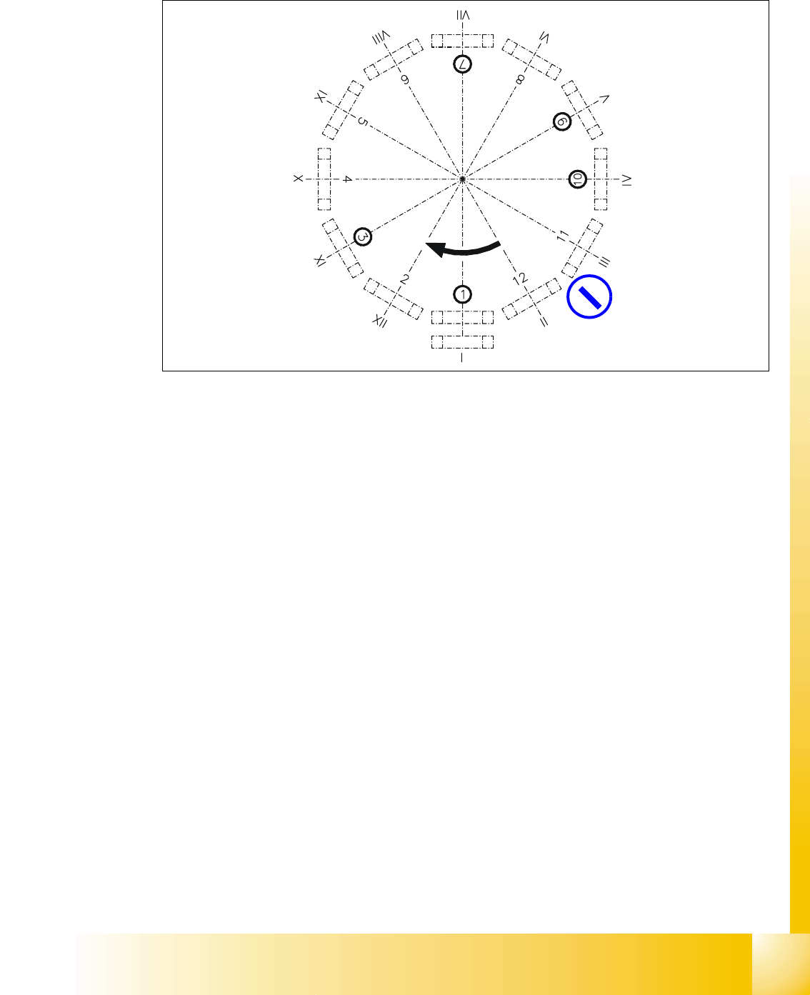
6.1.2 Position and function of the individual star stations
Fig. 6.1 - 2 Overview of the functions of star stations 1 - 12 I-XII segment numbers
I-XIISegment numbering
Star station 1: pick up, place and reject component 6
Star station 2: no function 6
Star station 3: no function (at HF/HF3 machine) 6
Star station 4, 5 and 6: no function 6
Star station 7: optically center component 6
Star station 8: no function 6
Star station 9: rotate component 6
Star station 10: position for removing and inserting sleeves 6
Star stations 11 and 12: no function (optionally Component sensor between star station 11 & 12)6
optionally:
Component sensor