SiplaceX4_en.pdf - 第236页
1 - 8 S tudent Guide SIPLACE X 6 Collect &Place-He ad 6/12 Edition 09/2005 8 Star station 1 6 Pick-up cycle The nozzle is lowered onto the component. Once the valve po sitioning unit has opened the vac- uum circuit t…
1 - 7
Student Guide SIPLACE X
Edition 09/2005 6 Collect &Place-Head 6/12
7
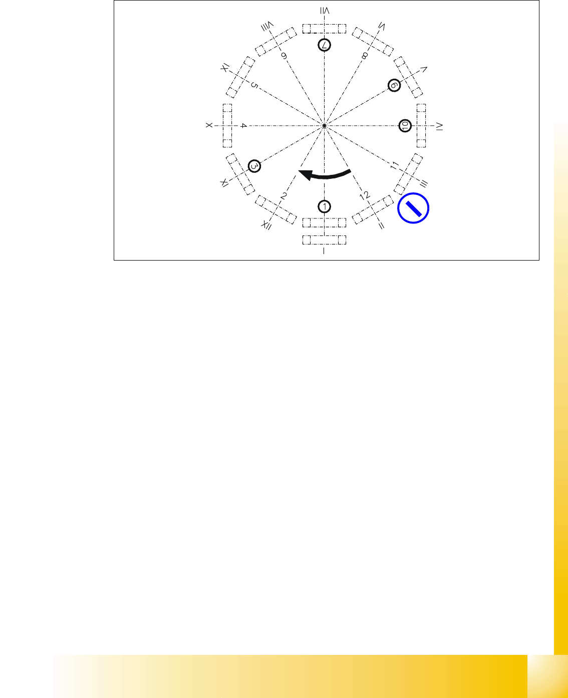
6.1.2 Position and function of the individual star stations
Fig. 6.1 - 2 Overview of the functions of star stations 1 - 12 I-XII segment numbers
I-XIISegment numbering
Star station 1: pick up, place and reject component 6
Star station 2: no function 6
Star station 3: no function (at HF/HF3 machine) 6
Star station 4, 5 and 6: no function 6
Star station 7: optically center component 6
Star station 8: no function 6
Star station 9: rotate component 6
Star station 10: position for removing and inserting sleeves 6
Star stations 11 and 12: no function (optionally Component sensor between star station 11 & 12)6
optionally:
Component sensor

1 - 8
Student Guide SIPLACE X
6 Collect &Place-Head 6/12 Edition 09/2005
8
Star station 1 6
Pick-up cycle
The nozzle is lowered onto the component. Once the valve positioning unit has opened the vac-
uum circuit to the nozzle, the nozzle draws up the component and removes it from the feeder mod-
ule.
Placement cycle
The nozzle, together with the component, is lowered onto the PCB that has been moved into
place. The valve positioning unit closes the vacuum channel to the nozzle. A short burst of com-
pressed air detaches the component from the nozzle and places it on the PCB.
Reject cycle
After the gantry reach the X- and Y-reject position the valve positioning unit closes the vacuum
channel to the nozzle. Defective components are detached from the nozzle with a short burst of
compressed air and are discarded.
Star station 7 6
The component is optically centered. 6
Star station 9 6
Pick-up cycle 6
The nozzle is rotated to the pick-up position. 6
Placement cycle
The component is rotated to the placement position (angle of rotation).
Star station 10 6
The SW move nozzles and sleeves to here for checking. 6
between Star station 11&12 6
Option on 12 nozzle head:
The component height is optically checked before placement.
6
1 - 9
Student Guide SIPLACE X
Edition 09/2005 6 Collect &Place-Head 6/12
9
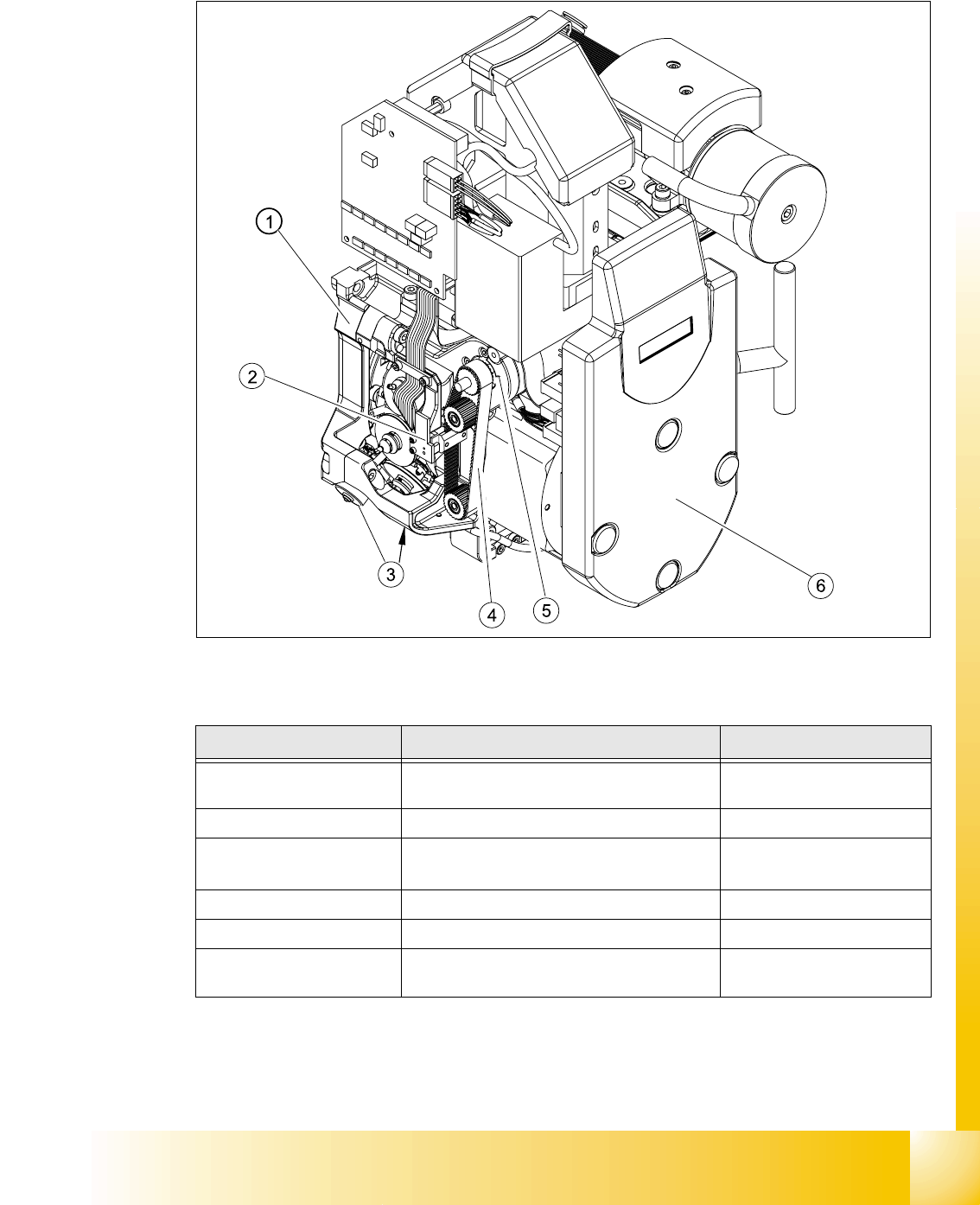
6.1.3 Overview parts on the 12 Segment C&P head
6
Fig. 6.1 - 3 DLM2 Collect&Place head - parts overview 1
Item Designation Item no.
1
Collect&place head SP12 complete / DLM2
Collect&place head SP6 complete / DLM2
00367281-02
00367020-01
2 Light barrier for "Z-axis up" 00347297-01
3
Valve positioning drive, placement circuit
Valve positioning drive, reject circuit
00368075-01
00367768-01
4 Toothed belt T2 / DLM2 00334936-01
5 Z-axis drive / DLM2 00341011-01
6
SP6_12 intermediate distribution board, digi-
tal (behind the cover) 00330648-05