SiplaceX4_en.pdf - 第24页
1 - 16 S tudent Guide SIPLACE X 1 Operational safety Edition 09/2005 16 1.4 ESD guidelines 1.4.1 Handling ESD modules Do not touch e lectronic modules unless it is ab solute ly essential to do so in orde r to carry out o…
1 - 15
Student Guide SIPLACE X
Edition 09/2005 1 Operational safety
15
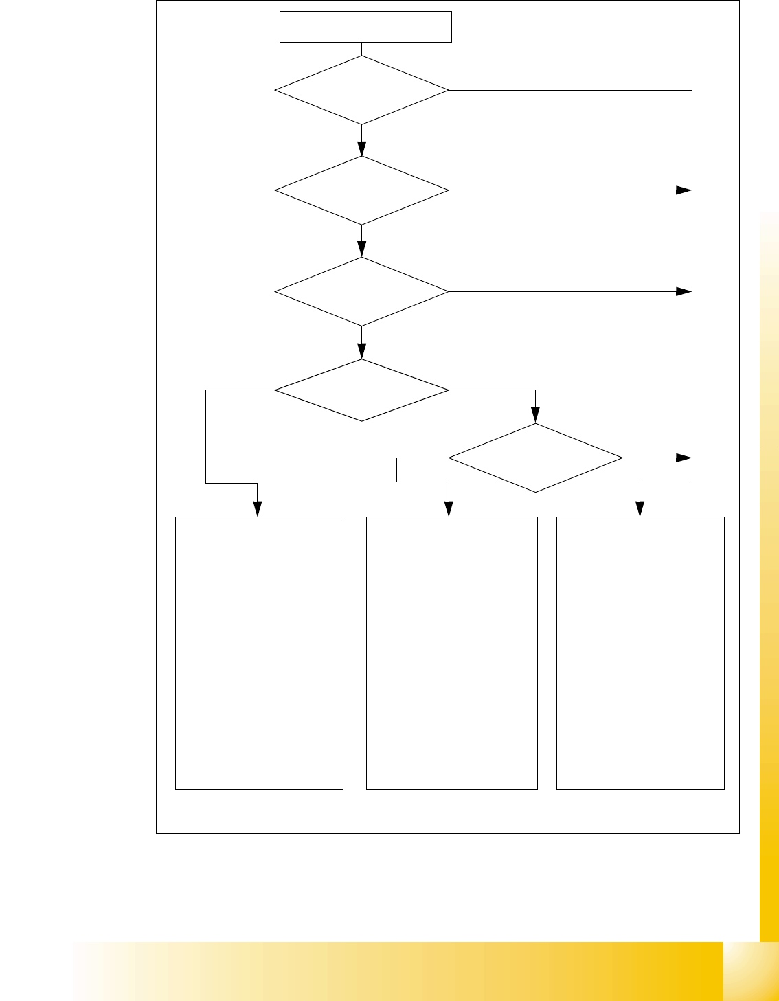
Fig. 1.3 - 4 Safety circuits
Start button pressed
Compressed air
min. 0.5 MPa
(5.0 bar)?
No
Emerg. stop
push-button pressed?
Protective cover open ?
Safety mode
activated on the user
interface?
No
Component
trolley safety circuit
interrupted?
Yes
No
No
Yes
Yes
No
Active
PCC*) Yes
Voltage
Y axis 250 V-
X axis 250 V-
star axis 145 V-
DP axis/D-Twin 40 V-
Z axis/Z-Twin 40 V-
Active
PCB conveyor Yes
Lifting table Yes
PCB clamping Yes
Width adjustment Yes
Laser light barrier Yes
Tape cutter Yes
CO trolley dock. unit Yes
Yes
Active
PCC*) No
Voltage
Y axis 0 V
X axis 0 V
star axis 0 V-
DP axis/D-Twin 40 V-
Z axis/Z-Twin 40 V-
Active
PCB conveyor Yes
Lifting table No
PCB clamping No
Width adjustment Yes
Laser light barrier No
Tape cutter No
CO trolley dock. unit Yes
Active
PCC*) No
Voltage
Y axis 0 V
X axis 0 V
star axis 0 V-
DP axis/D-Twin 40 V-
Z axis/Z-Twin 40 V-
Active
PCB conveyor No
Lifting table No
PCB clamping No
Width adjustment No
Laser light barrier No
Tape cutter No
CO trolley dock. unit No
*) PCC protective contactor combination K6
Yes
Start button pressed

1 - 16
Student Guide SIPLACE X
1 Operational safety Edition 09/2005
16
1.4 ESD guidelines
1.4.1 Handling ESD modules
Do not touch electronic modules unless it is absolutely essential to do so in order to carry out other
work. If it is necessary, make sure that you do not touch the pins or printed conductors when you
pick up flat modules.
Do not touch components unless
➠ you are constantly earthed by an ESD wrist strap or
➠ you are wearing ESD shoes or ESD shoe earthing strips on an ESD floor.
Always discharge yourself before you touch an electronic module. To do this, simply touch a con-
ductive and earthed object immediately before you touch the module (such as unpainted parts of
a switch cabinet, a water pipe, etc.).
Do not allow modules with chargeable and highly insulating materials to touch one another, e.g.
plastic films, insulating table surfaces or items of clothing made from synthetic fibers.
Always place the modules on a conductive surface (table with an ESD coating, conductive ESD
foam, ESD bag or container).
Do not bring modules near visual display units, monitors or televisions. Keep them at least 10 cm
away from the screen.
1.4.2 Measurements and modifications to ESD modules
Do not take measurements on such modules unless
– the measuring device is earthed (e.g. via PE conductors) or
– you discharge the measuring head just before taking measurements with a potential-free mea-
suring device (e.g. by touching an unpainted metal part of the controller casing).
➠ Always use an earthed soldering iron if you carry out any soldering work.
1.4.3 Dispatching ESD modules
➠ Always store modules and components in conductive packaging (e.g. metallized plastic bags
or metal sleeves) and dispatch them in conductive packaging.
If the packaging is not conductive, place the modules in a conductive envelope before packag-
ing. (Use ESD bags, domestic aluminum foil or paper, for example. NEVER use plastic bags
or film). 1
➠ If the module has integral batteries, ensure that the conductive packaging does not touch or
short-circuit the battery terminals and, if necessary, first cover the terminals with insulating tape
or material.

Student Guide SIPLACE X
Edition 09/2005 Contents
1
Chapter
Table of Contents
2 Overview . . . . . . . . . . . . . . . . . . . . . . . . . . . . . . . . . . . . . . . . . . . . . . . . . . . . . . . . . . 3
2.1 General . . . . . . . . . . . . . . . . . . . . . . . . . . . . . . . . . . . . . . . . . . . . . . . . . . . . . . . . . . . . . . . . . . . . . . . . 3
2.1.1 Specification and Configuration of Siplace X. . . . . . . . . . . . . . . . . . . . . . . . . . . . . . . . 5
2.2 Overview of Units. . . . . . . . . . . . . . . . . . . . . . . . . . . . . . . . . . . . . . . . . . . . . . . . . . . . . . . . . . . . . . . . 9
2.2.1 Power supply unit . . . . . . . . . . . . . . . . . . . . . . . . . . . . . . . . . . . . . . . . . . . . . . . . . . . 10
2.2.1.1 Overview of Voltages in the Power Supply Unit . . . . . . . . . . . . . . . . . . . . . . . . . 10
2.2.2 Pneumatic unit. . . . . . . . . . . . . . . . . . . . . . . . . . . . . . . . . . . . . . . . . . . . . . . . . . . . . . 12
2.2.2.1 Pneumatic Circuit for Cooling the Y - Linear Motor for Placement Area 1/2 . . . 13
2.2.2.2 Pneumatic Circuit for Cooling the X - Linear Motor for Placement Area 1/2 . . . 13
2.2.2.3 Compressed Air Distributor Block. . . . . . . . . . . . . . . . . . . . . . . . . . . . . . . . . . . . 13
2.2.3 Sectors 1 - 4 . . . . . . . . . . . . . . . . . . . . . . . . . . . . . . . . . . . . . . . . . . . . . . . . . . . . . . . 14
2.2.4 Computer Unit . . . . . . . . . . . . . . . . . . . . . . . . . . . . . . . . . . . . . . . . . . . . . . . . . . . . . . 15
2.2.5 Axis Unit . . . . . . . . . . . . . . . . . . . . . . . . . . . . . . . . . . . . . . . . . . . . . . . . . . . . . . . . . . 16
2.2.5.1 Example of Axis Unit for X4/ X3 with Two C&P20 Heads in Placement Area 1. 16
2.2.5.2 Example of Axis Unit for X4/ X3 with Two DLM Heads in Placement Area 1. . . 17
2.2.5.3 Example of Axis Unit for X3/ X2 with Twin Head in Placement Area 2 . . . . . . . 18
2.2.5.4 Axis Card A363 . . . . . . . . . . . . . . . . . . . . . . . . . . . . . . . . . . . . . . . . . . . . . . . . . 19
2.2.6 Component changeover tables . . . . . . . . . . . . . . . . . . . . . . . . . . . . . . . . . . . . . . . . . 20
2.2.6.1 Docking and Undocking . . . . . . . . . . . . . . . . . . . . . . . . . . . . . . . . . . . . . . . . . . . 20
2.2.6.2 Adjusting the Changeover Table Height. . . . . . . . . . . . . . . . . . . . . . . . . . . . . . . 21
2.2.6.3 Overview of X-Feeder. . . . . . . . . . . . . . . . . . . . . . . . . . . . . . . . . . . . . . . . . . . . . 22
2.2.6.4 Overview S-Feeders. . . . . . . . . . . . . . . . . . . . . . . . . . . . . . . . . . . . . . . . . . . . . . 23
2.2.7 Construction of the X-Axis . . . . . . . . . . . . . . . . . . . . . . . . . . . . . . . . . . . . . . . . . . . . 24
2.2.7.1 X-Axis Technical Data . . . . . . . . . . . . . . . . . . . . . . . . . . . . . . . . . . . . . . . . . . . . 25
2.2.8 Construction of the Y-axis . . . . . . . . . . . . . . . . . . . . . . . . . . . . . . . . . . . . . . . . . . . . . 26
2.2.9 Siplace Vision . . . . . . . . . . . . . . . . . . . . . . . . . . . . . . . . . . . . . . . . . . . . . . . . . . . . . . 27
2.2.9.1 Digital PCB Camera (Multicolor). . . . . . . . . . . . . . . . . . . . . . . . . . . . . . . . . . . . . 27
2.2.9.2 Digital Component Camera for 12-Segment C&P Head . . . . . . . . . . . . . . . . . . 28
2.2.9.3 Component Camera for 6-Segment C&P Head . . . . . . . . . . . . . . . . . . . . . . . . . 29
2.2.9.4 Component Camera for 20-Segment C&P Head . . . . . . . . . . . . . . . . . . . . . . . . 30
2.2.9.5 Stationary IC Camera. . . . . . . . . . . . . . . . . . . . . . . . . . . . . . . . . . . . . . . . . . . . . 31
2.2.9.6 Flip - Chip (FC) Camera (Optional) . . . . . . . . . . . . . . . . . . . . . . . . . . . . . . . . . . 32
2.2.10 C&P Head Type DLM2 with 12/6 Segments . . . . . . . . . . . . . . . . . . . . . . . . . . . . . . 33
2.2.10.1 Steps When Picking Up and Placing Components. . . . . . . . . . . . . . . . . . . . . . 34
2.2.10.2 Position and Function of the Individual Star Stations (see Fig. 2.2 - 21) . . . . . 34
2.2.10.3 Function Overview for Star Stations 1 - 12. . . . . . . . . . . . . . . . . . . . . . . . . . . . 35
2.2.10.4 Nozzle changer for 12 segment C&P head . . . . . . . . . . . . . . . . . . . . . . . . . . . 36
2.2.10.5 Nozzle changer for 6 segment C&P head . . . . . . . . . . . . . . . . . . . . . . . . . . . . 37