SiplaceX4_en.pdf - 第249页
1 - 21 S tudent Guide SIPLACE X Edition 09/2005 6 Coll ect &Place-Head 6/12 21 6.2.5 Reference Run at Dp-axis The function of the DP axis is, to turn the nozzl e in the correct p ick up angle. Af ter the component re…
1 - 20
Student Guide SIPLACE X
6 Collect &Place-Head 6/12 Edition 09/2005
20
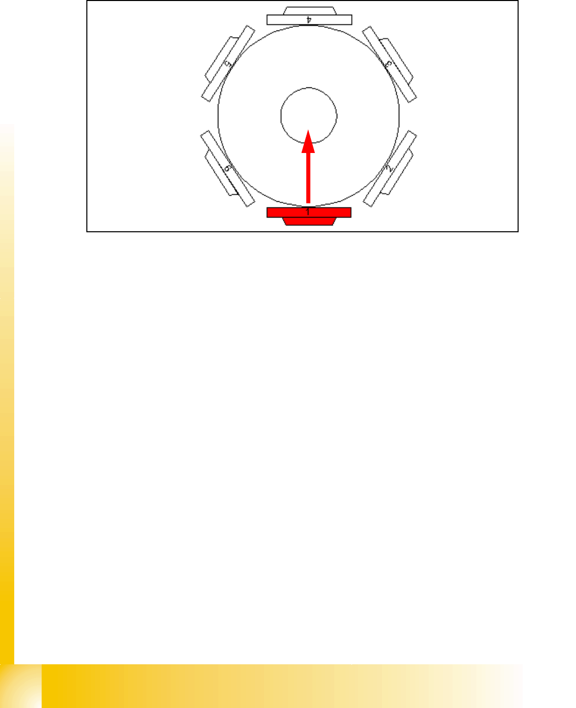
6.2.4 Completion of the Z-axis Reference Run
Fig. 6.2 - 6 Completion of the Z-axis reference run
– The Star-axis turns to 6250 digit(HF)2500(X4/X3/X2). At this position the segment ball bearing
is exactly between Z-claw and circular guidance.
– Z-axis moves to the upper end stop and takes the position. The same is done at the lower end
stop.
– The average value of these results is calculated and with a negative sign is loaded for refer-
ence value (ZPC) to the axis controller.
– Star-axis is moved back to reference position.
– Z-axis starts the reference run again with this new value.
1 - 21
Student Guide SIPLACE X
Edition 09/2005 6 Collect &Place-Head 6/12
21
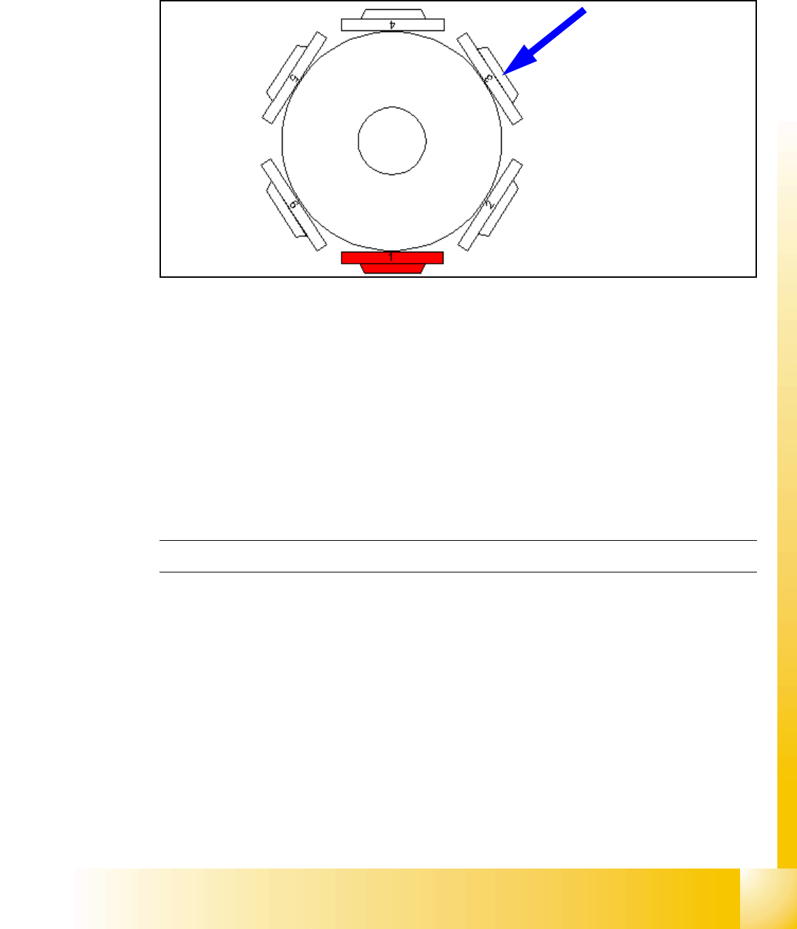
6.2.5 Reference Run at Dp-axis
The function of the DP axis is, to turn the nozzle in the correct pick up angle. After the component
recognition the DP-axis turn the components in correct placement angle.
Fig. 6.2 - 7 Reference run at DP-axis
– The segment now in the DP-station is turned to reference position. (Segment 3 at 6 nozzle
head / Segment 5 at 12 nozzle head.)
– Sequence: the DP-station swivels in. The axis starts and searches for the zero pulse. The Zero
pulse is checked on failure. The DP-station swivels out after the end signal.
– The swiveling function is controlled by the CAN-Bus.
– Turning the sleeve is controlled by the axis controller with signals from DP-position encoder.
– The zero point correction on the DP-axis is always 0 (because up to 12 segments are operated
by one drive).
C&P Head Reference run finished!
1 - 22
Student Guide SIPLACE X
6 Collect &Place-Head 6/12 Edition 09/2005
22
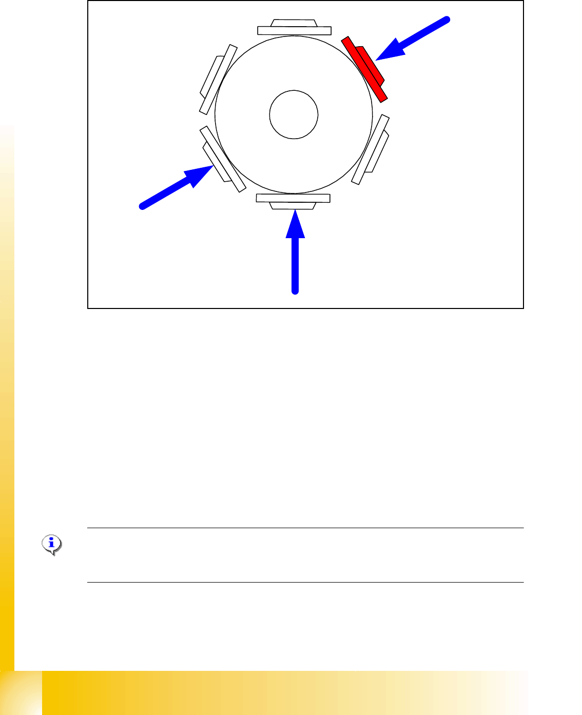
6.2.6 Pollution and Components are Rejected / Nozzles Turned to 0°
Fig. 6.2 - 8 Sequence vacuumcheck
– The Gantry axes move the Collect & Place head to the reject position.
– The star axes move anticlockwise and all three functions are carried out within a head cycle
and at same time (see Fig. 6.2 - 8).
1. The DP-station is swiveled in and turns each segment to 0° position.
2. The air kiss valve is opened, the valve drive of the reject position is activated and switches
between open and closed. Anything on the nozzle is rejected.The air kiss valve is closed.
3. The vacuum reference values at the pick-up
/ placement station are measured.
– These are the reference values for each segment for the vacuum checks during placement.
– These three steps are executed parallel.
Note:
The position 2 in Fig. 6.2 - 8 will used only on the X4 and X3/X2 Machine. The reject position on
the Siplace HF and SIPLACE X is below at position 3.
4
1
5
2
3
6
1
3
2