SiplaceX4_en.pdf - 第254页
1 - 26 S tudent Guide SIPLACE X 6 Collect &Place-He ad 6/12 Edition 09/2005 26 Notes:
1 - 25
Student Guide SIPLACE X
Edition 09/2005 6 Collect &Place-Head 6/12
25
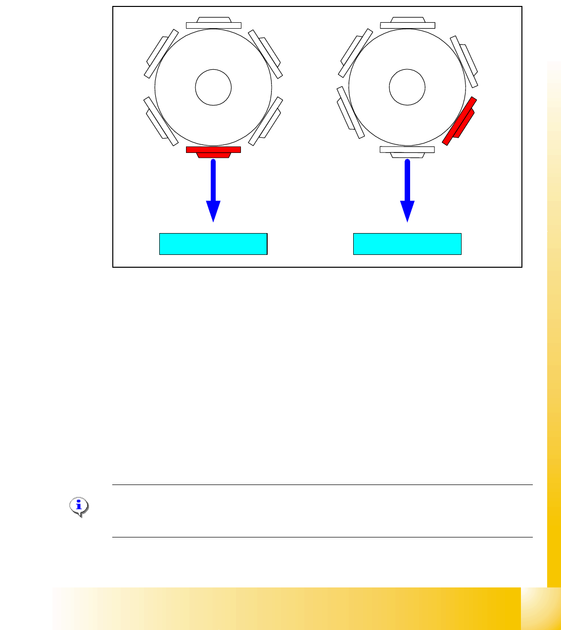
6.2.9 Height reference run
With this function we check the correct fitting on the sleeve and the correct nozzle type which is
programmed.
The nozzle length is taken to calculate the pick up and placement height for the following place-
ments.
Fig. 6.2 - 11 Measure nozzle height
1. Top of the fixed conveyor rail
2. First step with segment 1 for measure the nozzle height.
3. Last step with segment 6 (12) for measure the nozzle height.
– The gantry moves the placement heads above the fixed conveyor rail.
– The Z- axis runs down, and all nozzles touch the transport rail.
– Nozzle 1 defines the reference length.
– All segments are measured according to there specific length reffering to nozzle 1.
– The maximum length tolerance is 0,4 mm: If the length difference is too high an error message
is displayed.
Please Note
Exception: special nozzle with type number X9X are only measured (there is no length specifica-
tion).
4
1
5
2
3
6
4
1
5
2
3
6
1
23
1 - 27
Student Guide SIPLACE X
Edition 09/2005 6 Collect &Place-Head 6/12
27
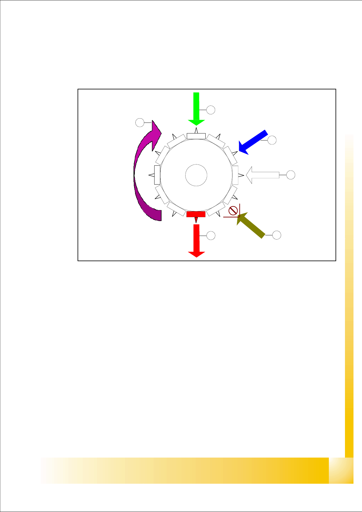
6.3 Placement sequence
6.3.1 Working positions at the placement head
Fig. 6.3 - 1 Working positions at the placement head
Key
(1) Optical centering
(2) turning station
(3) service position for segment; Removal of the sleeve on the opposite side
(4) pick up / placement / reject position
(5) working direction
(6) option: component sensor
12
1
1
1
0
9
8
7
6
5
1
2
3
4
1
2
3
4
5
6