SiplaceX4_en.pdf - 第26页
1 - 2 S tudent Guide SIPLACE X Contents Edition 09/2005 2 2.2.11 Twin Head . . . . . . . . . . . . . . . . . . . . . . . . . . . . . . . . . . . . . . . . . . . . . . . . . . . . . . . . 38 2.2.11.1 Description . . . . .…

Student Guide SIPLACE X
Edition 09/2005 Contents
1
Chapter
Table of Contents
2 Overview . . . . . . . . . . . . . . . . . . . . . . . . . . . . . . . . . . . . . . . . . . . . . . . . . . . . . . . . . . 3
2.1 General . . . . . . . . . . . . . . . . . . . . . . . . . . . . . . . . . . . . . . . . . . . . . . . . . . . . . . . . . . . . . . . . . . . . . . . . 3
2.1.1 Specification and Configuration of Siplace X. . . . . . . . . . . . . . . . . . . . . . . . . . . . . . . . 5
2.2 Overview of Units. . . . . . . . . . . . . . . . . . . . . . . . . . . . . . . . . . . . . . . . . . . . . . . . . . . . . . . . . . . . . . . . 9
2.2.1 Power supply unit . . . . . . . . . . . . . . . . . . . . . . . . . . . . . . . . . . . . . . . . . . . . . . . . . . . 10
2.2.1.1 Overview of Voltages in the Power Supply Unit . . . . . . . . . . . . . . . . . . . . . . . . . 10
2.2.2 Pneumatic unit. . . . . . . . . . . . . . . . . . . . . . . . . . . . . . . . . . . . . . . . . . . . . . . . . . . . . . 12
2.2.2.1 Pneumatic Circuit for Cooling the Y - Linear Motor for Placement Area 1/2 . . . 13
2.2.2.2 Pneumatic Circuit for Cooling the X - Linear Motor for Placement Area 1/2 . . . 13
2.2.2.3 Compressed Air Distributor Block. . . . . . . . . . . . . . . . . . . . . . . . . . . . . . . . . . . . 13
2.2.3 Sectors 1 - 4 . . . . . . . . . . . . . . . . . . . . . . . . . . . . . . . . . . . . . . . . . . . . . . . . . . . . . . . 14
2.2.4 Computer Unit . . . . . . . . . . . . . . . . . . . . . . . . . . . . . . . . . . . . . . . . . . . . . . . . . . . . . . 15
2.2.5 Axis Unit . . . . . . . . . . . . . . . . . . . . . . . . . . . . . . . . . . . . . . . . . . . . . . . . . . . . . . . . . . 16
2.2.5.1 Example of Axis Unit for X4/ X3 with Two C&P20 Heads in Placement Area 1. 16
2.2.5.2 Example of Axis Unit for X4/ X3 with Two DLM Heads in Placement Area 1. . . 17
2.2.5.3 Example of Axis Unit for X3/ X2 with Twin Head in Placement Area 2 . . . . . . . 18
2.2.5.4 Axis Card A363 . . . . . . . . . . . . . . . . . . . . . . . . . . . . . . . . . . . . . . . . . . . . . . . . . 19
2.2.6 Component changeover tables . . . . . . . . . . . . . . . . . . . . . . . . . . . . . . . . . . . . . . . . . 20
2.2.6.1 Docking and Undocking . . . . . . . . . . . . . . . . . . . . . . . . . . . . . . . . . . . . . . . . . . . 20
2.2.6.2 Adjusting the Changeover Table Height. . . . . . . . . . . . . . . . . . . . . . . . . . . . . . . 21
2.2.6.3 Overview of X-Feeder. . . . . . . . . . . . . . . . . . . . . . . . . . . . . . . . . . . . . . . . . . . . . 22
2.2.6.4 Overview S-Feeders. . . . . . . . . . . . . . . . . . . . . . . . . . . . . . . . . . . . . . . . . . . . . . 23
2.2.7 Construction of the X-Axis . . . . . . . . . . . . . . . . . . . . . . . . . . . . . . . . . . . . . . . . . . . . 24
2.2.7.1 X-Axis Technical Data . . . . . . . . . . . . . . . . . . . . . . . . . . . . . . . . . . . . . . . . . . . . 25
2.2.8 Construction of the Y-axis . . . . . . . . . . . . . . . . . . . . . . . . . . . . . . . . . . . . . . . . . . . . . 26
2.2.9 Siplace Vision . . . . . . . . . . . . . . . . . . . . . . . . . . . . . . . . . . . . . . . . . . . . . . . . . . . . . . 27
2.2.9.1 Digital PCB Camera (Multicolor). . . . . . . . . . . . . . . . . . . . . . . . . . . . . . . . . . . . . 27
2.2.9.2 Digital Component Camera for 12-Segment C&P Head . . . . . . . . . . . . . . . . . . 28
2.2.9.3 Component Camera for 6-Segment C&P Head . . . . . . . . . . . . . . . . . . . . . . . . . 29
2.2.9.4 Component Camera for 20-Segment C&P Head . . . . . . . . . . . . . . . . . . . . . . . . 30
2.2.9.5 Stationary IC Camera. . . . . . . . . . . . . . . . . . . . . . . . . . . . . . . . . . . . . . . . . . . . . 31
2.2.9.6 Flip - Chip (FC) Camera (Optional) . . . . . . . . . . . . . . . . . . . . . . . . . . . . . . . . . . 32
2.2.10 C&P Head Type DLM2 with 12/6 Segments . . . . . . . . . . . . . . . . . . . . . . . . . . . . . . 33
2.2.10.1 Steps When Picking Up and Placing Components. . . . . . . . . . . . . . . . . . . . . . 34
2.2.10.2 Position and Function of the Individual Star Stations (see Fig. 2.2 - 21) . . . . . 34
2.2.10.3 Function Overview for Star Stations 1 - 12. . . . . . . . . . . . . . . . . . . . . . . . . . . . 35
2.2.10.4 Nozzle changer for 12 segment C&P head . . . . . . . . . . . . . . . . . . . . . . . . . . . 36
2.2.10.5 Nozzle changer for 6 segment C&P head . . . . . . . . . . . . . . . . . . . . . . . . . . . . 37

1 - 2
Student Guide SIPLACE X
Contents Edition 09/2005
2
2.2.11 Twin Head . . . . . . . . . . . . . . . . . . . . . . . . . . . . . . . . . . . . . . . . . . . . . . . . . . . . . . . . 38
2.2.11.1 Description . . . . . . . . . . . . . . . . . . . . . . . . . . . . . . . . . . . . . . . . . . . . . . . . . . . . 38
2.2.11.2 Nozzle Changer for Twin Head. . . . . . . . . . . . . . . . . . . . . . . . . . . . . . . . . . . . . 39
2.2.12 C&P20 Head . . . . . . . . . . . . . . . . . . . . . . . . . . . . . . . . . . . . . . . . . . . . . . . . . . . . . . 40
2.2.12.1 Description . . . . . . . . . . . . . . . . . . . . . . . . . . . . . . . . . . . . . . . . . . . . . . . . . . . . 41
2.2.12.2 Overview of Functions for Star Stations 1 - 20 . . . . . . . . . . . . . . . . . . . . . . . . . 42
2.2.12.3 Nozzle Changer for C&P20 Head. . . . . . . . . . . . . . . . . . . . . . . . . . . . . . . . . . . 43
2.2.13 Conveyor system . . . . . . . . . . . . . . . . . . . . . . . . . . . . . . . . . . . . . . . . . . . . . . . . . . . 44
2.2.13.1 General. . . . . . . . . . . . . . . . . . . . . . . . . . . . . . . . . . . . . . . . . . . . . . . . . . . . . . . 44
2.2.13.2 Construction of Single Conveyor . . . . . . . . . . . . . . . . . . . . . . . . . . . . . . . . . . . 46
2.2.13.3 Construction of Dual Conveyor. . . . . . . . . . . . . . . . . . . . . . . . . . . . . . . . . . . . . 46
1 - 3
Student Guide SIPLACE X
Edition 09/2005 2 Overview
3
2 Overview
2.1 General
The Siplace X machine generation is characterized by its excellent configuration options, high
flexibility and the greatest possible accuracy. The versions in this new series - SIPLACE X2
(2 gantries), SIPLACE X3 (3 gantries) and SIPLACE X4 (4 gantries) machines - cover placement
of the entire SMD component spectrum.
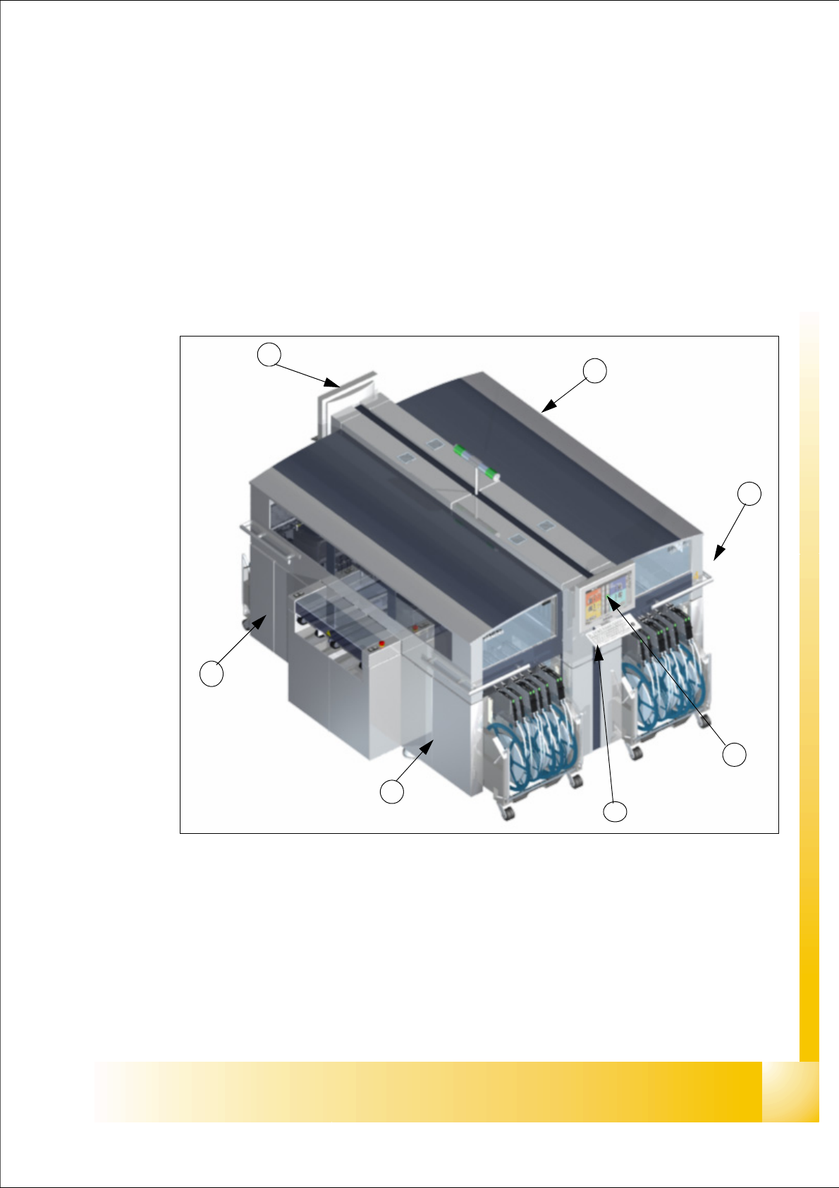
Fig. 2.1 - 1 Overview of Siplace X
Key:
(1) Sector 1 (2) Sector 2
(3) Sector 3 (4) Sector 4
(5) Monitor (on both side) (6) Keyboard (on both side)
5
5
6
4
1
2
3