SiplaceX4_en.pdf - 第262页
1 - 34 S tudent Guide SIPLACE X 6 Collect &Place-He ad 6/12 Edition 09/2005 34 6.3.13 Pick up 12th component Fig. 6.3 - 13 Pick up 12th component 6.3.14 Placing 1st component Fig. 6.3 - 14 Placing 1st component St ar…
1 - 33
Student Guide SIPLACE X
Edition 09/2005 6 Collect &Place-Head 6/12
33
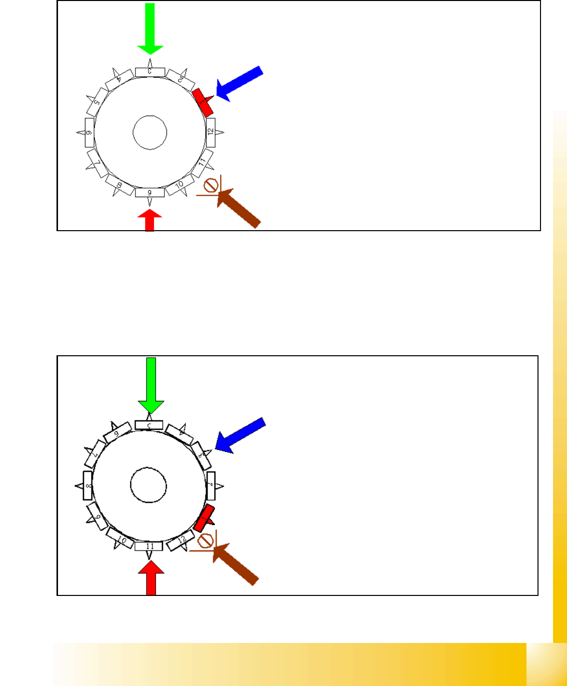
6.3.11 Pick up 9th Component
Fig. 6.3 - 11 Pick up 9th component
The process continues with the remaining components being picked up, centred and turned to the
corrected placement angle.
6.3.12 Component recognition at the 1
st
Segment in Component Sensor
Fig. 6.3 - 12 Pick up 11
th
component and comp. recognition at 1
st
segment
Star position 240°
– Vision system: optical centering of the 3rd component
– DP-station: turn 1st component to the placement an-
gle
– pick up / placement station: pick up 9th component
– component sensor: during the next Star step the noz-
zle length of segment 11 is measured
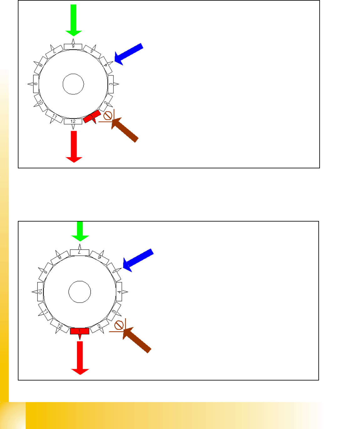
Star turns to -> 330°
During the Star-axis is turning from 300.000 to
330.000 Digit.
– the component sensor (option) measures the pres-
ence resp. the height of the component.
– The measured length before placement have to be
larger than "nozzle length + comp.height -
comp.height tol."
– The measurement in the component sensor hap-
pens at full movement of the star axis -"on the fly"- .
A defective component is rejected at the next
pickup cycle.
1 - 34
Student Guide SIPLACE X
6 Collect &Place-Head 6/12 Edition 09/2005
34
6.3.13 Pick up 12th component
Fig. 6.3 - 13 Pick up 12th component
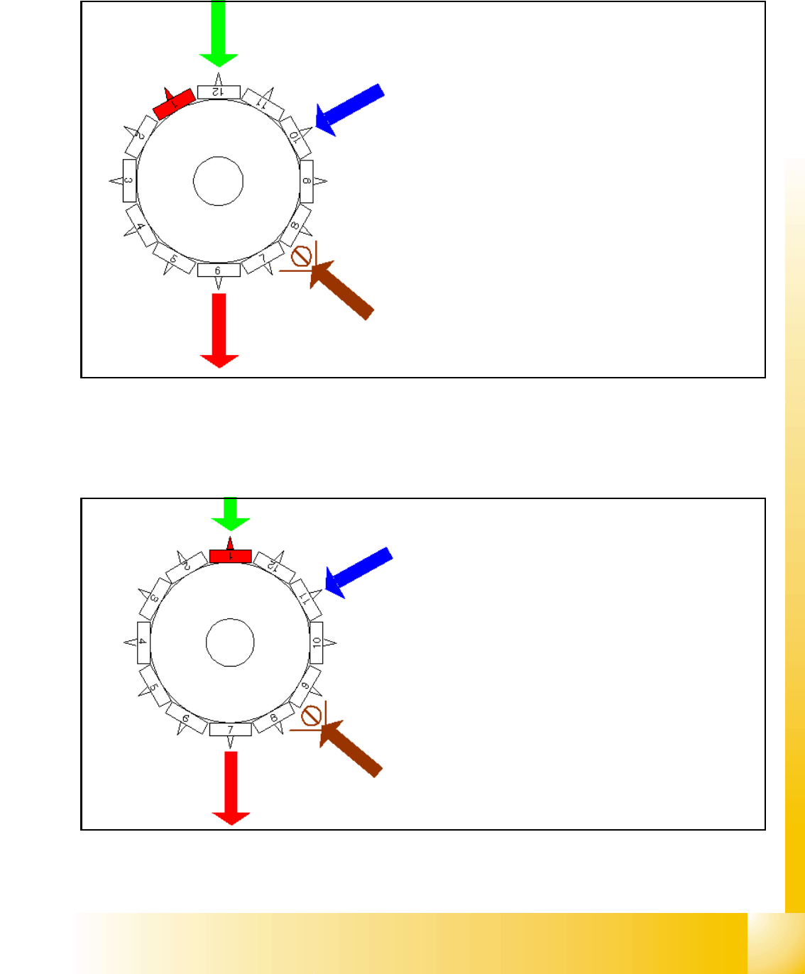
6.3.14 Placing 1st component
Fig. 6.3 - 14 Placing 1st component
Star position 330°
– Vision system: optical centering of the 6th com-
ponent
– DP-station: turn 4th component to the placement
angle
– pick up / placement station: pick up 12th compo-
nent
– communication with the component table: acti-
vate tape cutter
– synchronization: after picking the 12th compo-
nent this gantry is waiting for placement enable
signal from MC.
– component sensor:during the next Star step the
comp. presence or comp. height at segment 2 is
measured.
Star position 0°
– Vision system: optical centering of the 7th com-
ponent
– DP-station: turn 5th component to the place-
ment angle
– pick up / placement station: place 1st compo-
nent
– component sensor (option) during the next Star
step the comp. presence or comp. height at seg-
ment 3 is measured.
The process continues for the remaining nozzles
1 - 35
Student Guide SIPLACE X
Edition 09/2005 6 Collect &Place-Head 6/12
35
6.3.15 Placing 6th component
Fig. 6.3 - 15 Placing 6th component
6.3.16 Placing 7th Component
Fig. 6.3 - 16 Placing 7th component
Star position 150°
– Vision system: optical centering of the 12th compo-
nent
– DP-station: turn 10th component to the placement
angle
– pick up / placement station: place 6th component
– synchronization: communication with the MVS for
the optical centering of component´s on the other
gantry.
– component sensor: during the next Star step the
comp. presence or comp. height at segment 8 is
measured.
Star position 180°
– Vision system: optical centering of the 1st component
on the other gantry
– DP-station: turn 11th component to the placement an-
gle
– pick up / placement station: place 7th component
– component sensor: during the next Star step the
comp. presence or comp. height at segment 9 is mea-
sured.