SiplaceX4_en.pdf - 第294页
1 - 66 S tudent Guide SIPLACE X 6 Collect &Place-He ad 6/12 Edition 09/2005 66 6.4.10 Air Pressure V alues 6.4.10.1 T ools and Devices – A set of slotted screw drivers – Compressed air testing device 6.4.10.2 Adjustm…
1 - 65
Student Guide SIPLACE X
Edition 09/2005 6 Collect &Place-Head 6/12
65
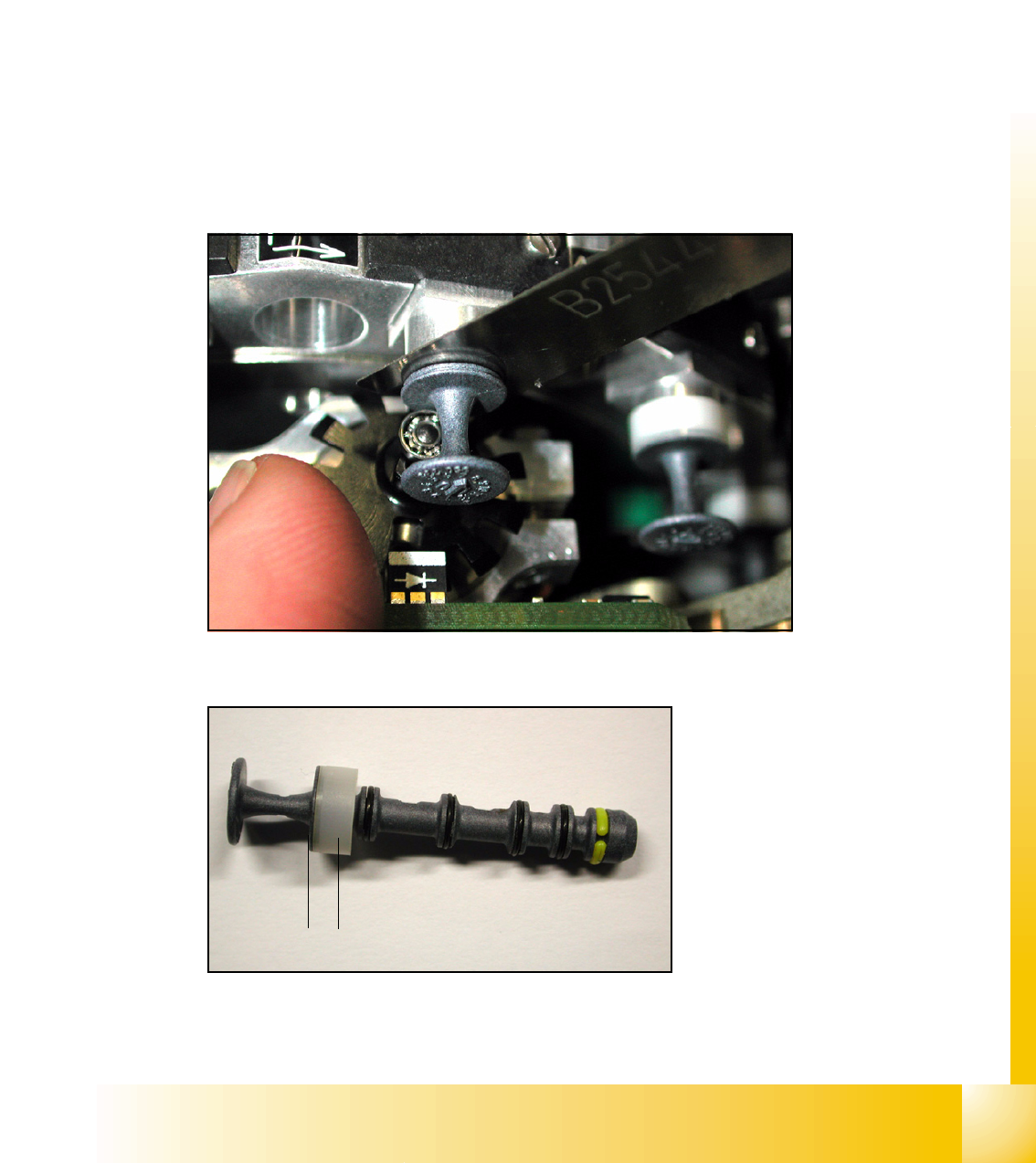
6.4.9 Adjustment of mechanical Position of Valve Drives
➠ If the new valve plungers are used (s. Fig. 6.4 - 13), proceed as follows:
– Take out one valve plunger and remove the plastic bushing
(2).
– Insert the plunger without bushing and carry out the following steps on this segment:
➠ Set the motor position of the valve drives "Pick-up / Placement" and "Ejection" according to the
figure below.
➠ Insert the distance gauge (0.2 mm) between valve plunger and valve casing.
➠ Turn the valve drive to 90° degrees, opposite to its initial position. The excentric of the valve
drive will just touch the inner flange of the valve.
➠ Fix the motor of the valve drive in this position.
➠ Don’t forget to refit the plastic bushing on the plunger.
6
Fig. 6.4 - 12 Mechanical position of the valve drive
6
Fig. 6.4 - 13 New Valve plunger, item.no:00351498-03
2
1

1 - 66
Student Guide SIPLACE X
6 Collect &Place-Head 6/12 Edition 09/2005
66
6.4.10 Air Pressure Values
6.4.10.1 Tools and Devices
– A set of slotted screw drivers
– Compressed air testing device
6.4.10.2 Adjustment of Air Pressure Values
6
Fig. 6.4 - 14 Adjustment of air pressure values
LEGEND:
(1) Forced air unit
(2) Solenoid valve for air kiss
(3) Adjustment valve for the reject circuit
(4) Adjustment valve for the pick - up / placement circuit
Please Note
:
Use a nozzle type 904 or 914 to adjust the air kiss. Please press in the spring from the nozzle
interface during the measurement and read the value from the display. 6
4
1
2
3
1 - 67
Student Guide SIPLACE X
Edition 09/2005 6 Collect &Place-Head 6/12
67
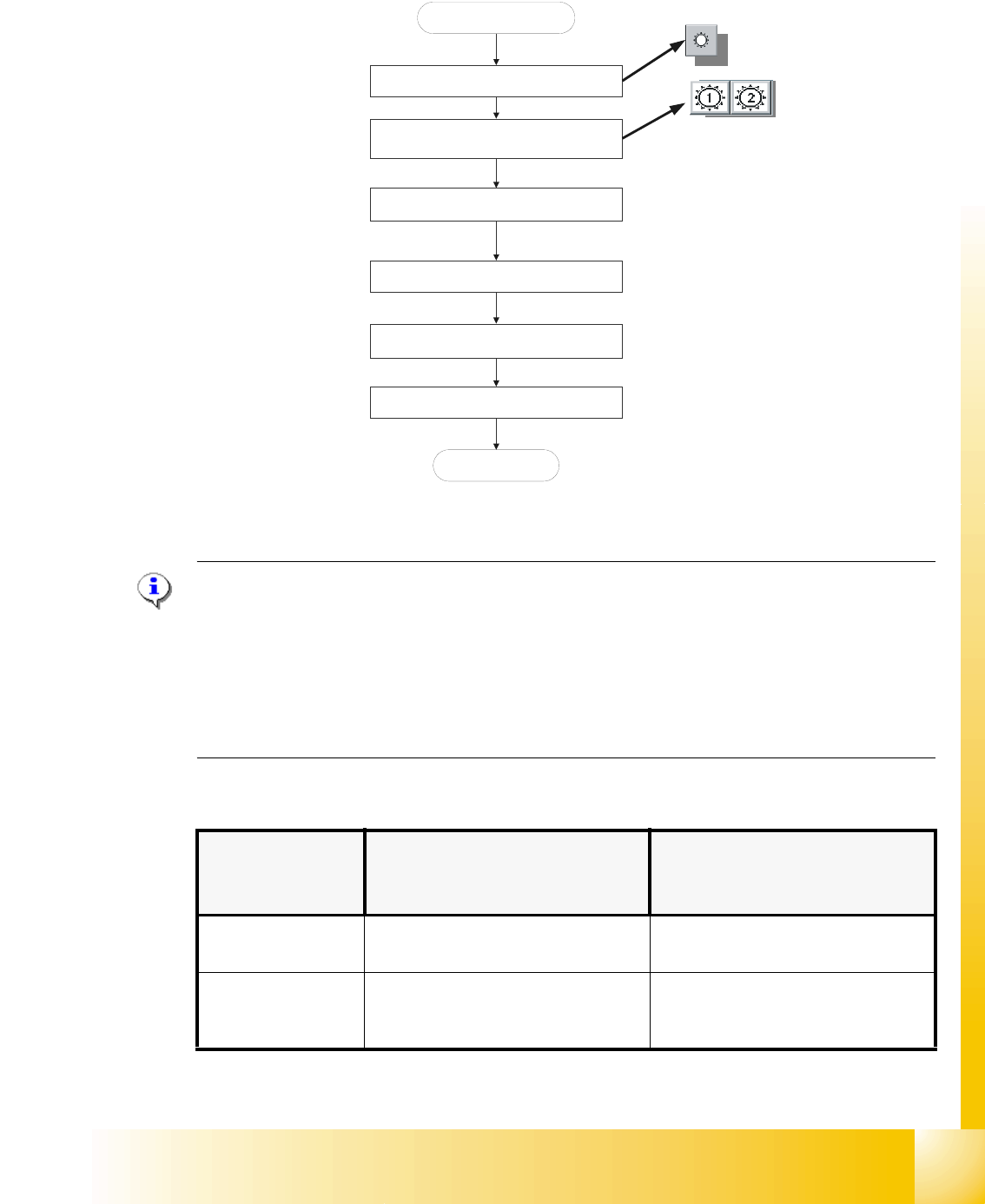
6.4.10.3 Adjustments of Air Pressure Values with the Compressed Air Testing Device
Fig. 6.4 - 15 Flow chart determining air pressure values
Please Note:
Air pressure values, displayed on the screen of the station computer, under option "Measure air
pressure" of the "Single functions", or in the SITEST program, do not correspond to the air
pressure values actually set at the nozzles.
They solely serve to check that the forced air valve is functioning correctly.
Therefore, the air pressure may not be adjusted with the values displayed on the screen.
Instead, use only the values determined with the compressed air testing device. 6
➠ Adjust to the values of the table below:
Air kiss function
circuits
Adjustment with Compressed Air
Testing Device
Measurement taken on Nozzle
Displayed on the Monitor:
(Only in Pick - Up and Placement
Circuit)
pick - up / placement
circuit
150 mbar (100 - 200 mbar) e.g.: 250 mbar
reject circuit
(not used for reject at
HFand X machine) 250 mbar (200 - 300 mbar) reject circuit does not have a sensor
Blast air “ON”
Placement and pick - up circuit
Select appropriate head
Collect & Place Heads
Start SITEST
Use compressed air testing device and
restrictor valve to adjust compressed air
Blast air “OFF”
End
Press the nozzle up, during the
measurement procedure