SiplaceX4_en.pdf - 第304页
1 - 76 S tudent Guide SIPLACE X 6 Collect &Place-He ad 6/12 Edition 09/2005 76 6 Fig. 6.6 - 3 Digital track signals head axes Please Note: The pulse width is dep endent on the speed , the phase locatio n is dependent…
1 - 75
Student Guide SIPLACE X
Edition 09/2005 6 Collect &Place-Head 6/12
75
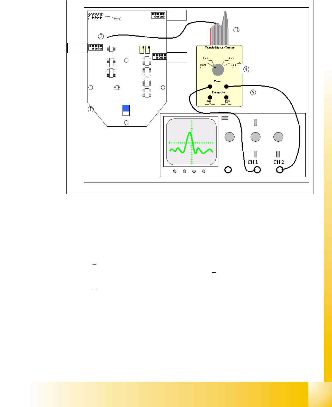
6.6.2.2 Test set up
Fig. 6.6 - 2 General test set up to check the track signals
X13 = Z-Axis
X15 = Star-Axis
X16 = DP-Axis 6
Connector description of the connectors X13, X15, X16:
The track signals of the head axes can only be measured as digital signals i.e. the transformation
of the analogous track signals into digital track signals occurs directly in the incremental encoder.
X13
X16
X15
1. Ground 2. Track A
3. Track A
4. Ground
5. Track B 6. Track B
7. +5V 8. Track N
9. Track N
10.Pin removed
1 - 76
Student Guide SIPLACE X
6 Collect &Place-Head 6/12 Edition 09/2005
76
6
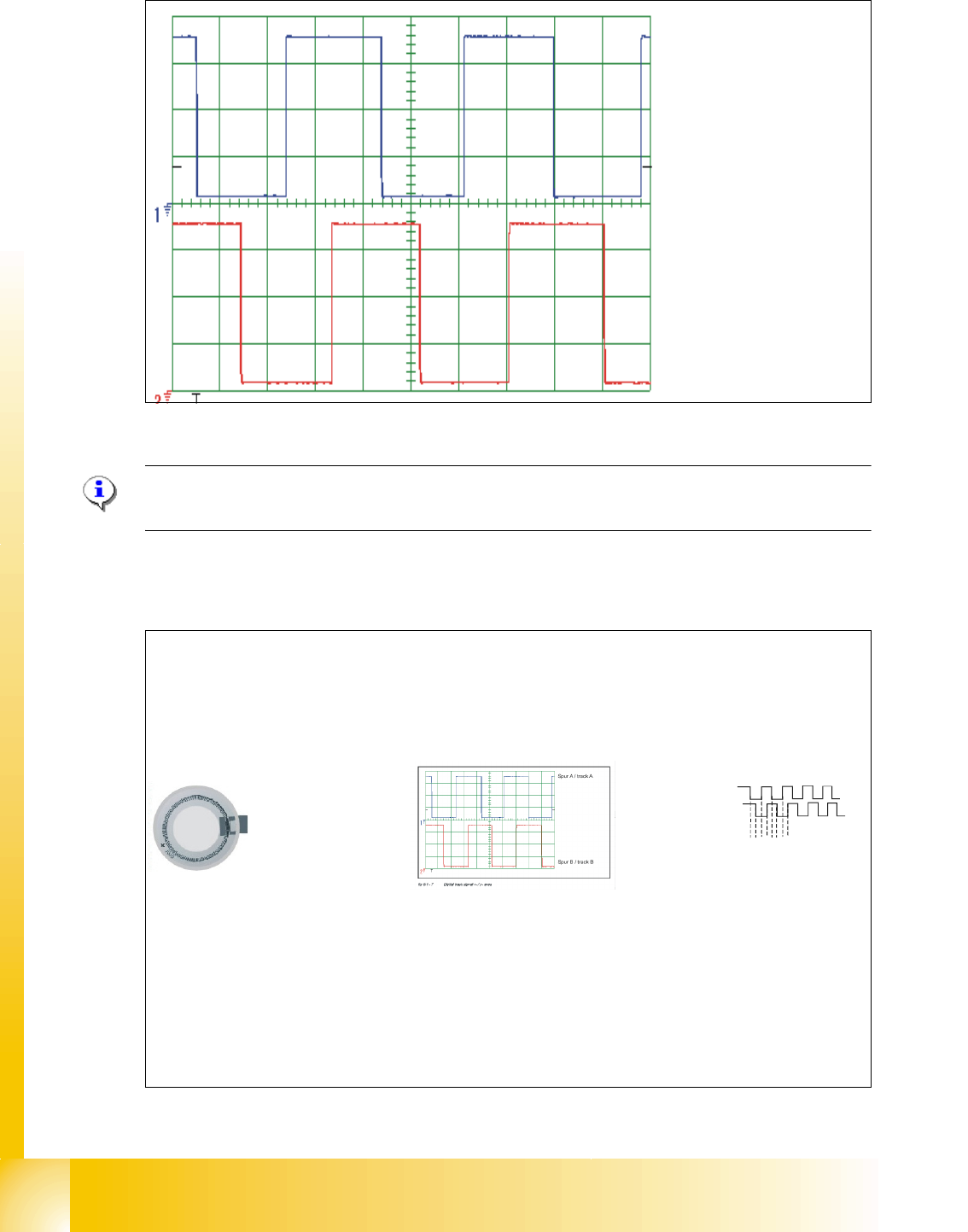
Fig. 6.6 - 3 Digital track signals head axes
Please Note:
The pulse width is dependent on the speed, the phase location is dependent on the direction. 6
6.6.2.3 Preparation of the track signals for control the star axis as example
Spur A / track A
Spur B / track B
Track Signal - Star Axis (not adjustable)
Digital Track Signal A, B and N
(zero
pulse) sent to Interm. Distributor Board.
Sensor
3.6 Vpp
Multiplication and Digitalization
of the Analogue
Track Signals A, and B
by
the
Digital Access
Controller on theInterm. Distributor Board.
(Multiplication by a factor of 25 for Digital Conversion)
Rotor
Scale
(3600 ticks / 360° of scale)
Incremental scale on the
DLM 2 C&P head
Transfer the track signals
to the axis board A 363
with VC3
12341234…..
Axis board A 363 with
VC3
Final Multiplication at Control
Unit Axis Decoder
.
(Multiplication by factor of 4)
End Result:
(3600) x (25) x (4) =
360.000 pulses / 360
°
Therefore ....
1° =1000 digit
1 digit = 0.001°
1 - 77
Student Guide SIPLACE X
Edition 09/2005 6 Collect &Place-Head 6/12
77
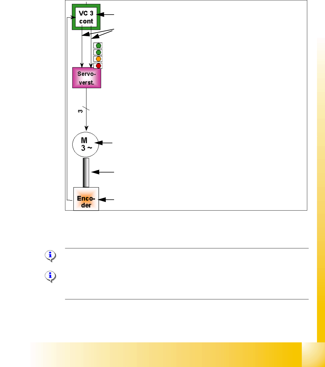
6.6.3 Axis control Star axis
The Star axis is driven with a 3 phase AC stepping motor with an intermediate circuit voltage of
120V. The control of the axis occurred with two control signals of the VC3 (dephasing 120°) con-
troller I
nom "W" and I nom "U". The third phase is calculated automatically.
Fig. 6.6 - 4 Axis closed control loop Star axis
6.6.3.1 Check the dynamic Star axis
Please Note:
For detailed notes to check the axis dynamic, please use the "Adjustment manual".
6
Please Note:
Before adjusting the axes, ensure that the machine has reached its operating temperature.
Switch the machine on at least 30 minutes before you begin work.
Axis card A363 with VC 3 Controller (VC = Velocity Commutation)
Control signals I
nom "W" and I nom "U"
LED‘s on the Servo amplifier:
– Power supply ON
– Servo enable, if the the enable signal from the axis board available.
– Display R.M.S. current limiter shorter than 2,5 s.
– Error: Overvoltage, -current, -temperature or Nominal current-overstep-
ping longer than 2,5 sec.
Servo board control directly the 3 phase AC motor.
3 Phasen AC Motor.
Between the motor and the incremental encoder exist a fixed mechanical
combination.
Incremental encoder: transmit the exact position of the axis via the track
signals.