SiplaceX4_en.pdf - 第305页
1 - 77 S tudent Guide SIPLACE X Edition 09/2005 6 Coll ect &Place-Head 6/12 77 6.6.3 Axis control St ar axis The S tar axis is driven with a 3 phase AC stepp ing motor with an intermed iate cir cuit volt age of 120V …
1 - 76
Student Guide SIPLACE X
6 Collect &Place-Head 6/12 Edition 09/2005
76
6
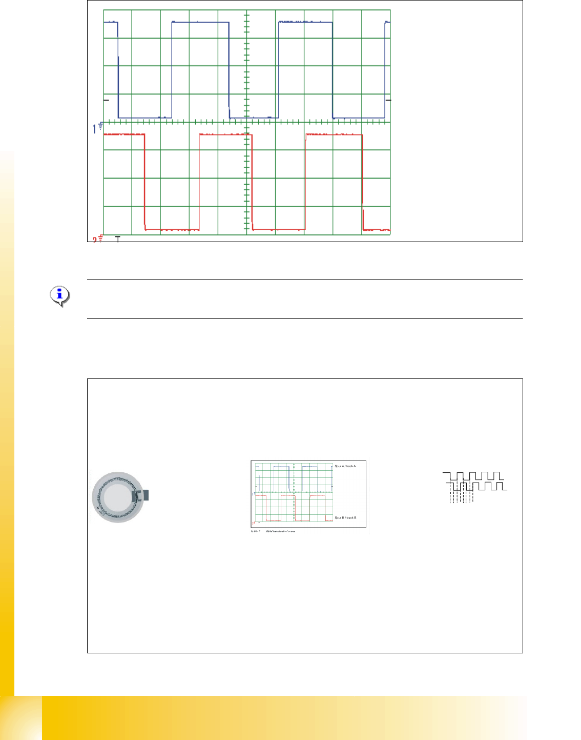
Fig. 6.6 - 3 Digital track signals head axes
Please Note:
The pulse width is dependent on the speed, the phase location is dependent on the direction. 6
6.6.2.3 Preparation of the track signals for control the star axis as example
Spur A / track A
Spur B / track B
Track Signal - Star Axis (not adjustable)
Digital Track Signal A, B and N
(zero
pulse) sent to Interm. Distributor Board.
Sensor
3.6 Vpp
Multiplication and Digitalization
of the Analogue
Track Signals A, and B
by
the
Digital Access
Controller on theInterm. Distributor Board.
(Multiplication by a factor of 25 for Digital Conversion)
Rotor
Scale
(3600 ticks / 360° of scale)
Incremental scale on the
DLM 2 C&P head
Transfer the track signals
to the axis board A 363
with VC3
12341234…..
Axis board A 363 with
VC3
Final Multiplication at Control
Unit Axis Decoder
.
(Multiplication by factor of 4)
End Result:
(3600) x (25) x (4) =
360.000 pulses / 360
°
Therefore ....
1° =1000 digit
1 digit = 0.001°
1 - 77
Student Guide SIPLACE X
Edition 09/2005 6 Collect &Place-Head 6/12
77
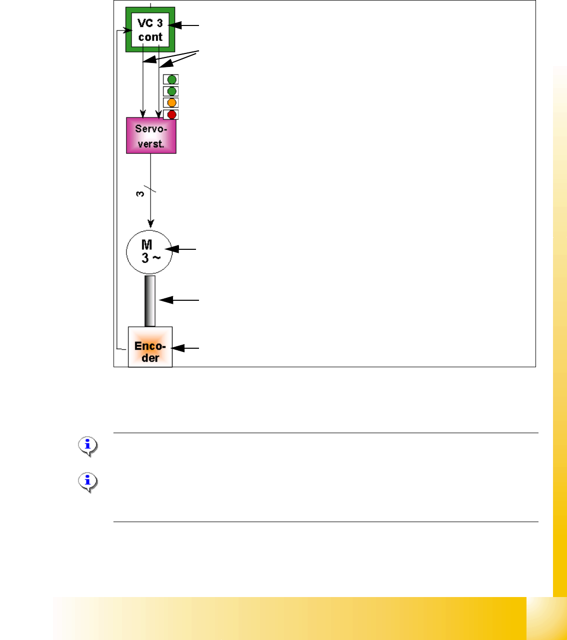
6.6.3 Axis control Star axis
The Star axis is driven with a 3 phase AC stepping motor with an intermediate circuit voltage of
120V. The control of the axis occurred with two control signals of the VC3 (dephasing 120°) con-
troller I
nom "W" and I nom "U". The third phase is calculated automatically.
Fig. 6.6 - 4 Axis closed control loop Star axis
6.6.3.1 Check the dynamic Star axis
Please Note:
For detailed notes to check the axis dynamic, please use the "Adjustment manual".
6
Please Note:
Before adjusting the axes, ensure that the machine has reached its operating temperature.
Switch the machine on at least 30 minutes before you begin work.
Axis card A363 with VC 3 Controller (VC = Velocity Commutation)
Control signals I
nom "W" and I nom "U"
LED‘s on the Servo amplifier:
– Power supply ON
– Servo enable, if the the enable signal from the axis board available.
– Display R.M.S. current limiter shorter than 2,5 s.
– Error: Overvoltage, -current, -temperature or Nominal current-overstep-
ping longer than 2,5 sec.
Servo board control directly the 3 phase AC motor.
3 Phasen AC Motor.
Between the motor and the incremental encoder exist a fixed mechanical
combination.
Incremental encoder: transmit the exact position of the axis via the track
signals.
1 - 78
Student Guide SIPLACE X
6 Collect &Place-Head 6/12 Edition 09/2005
78
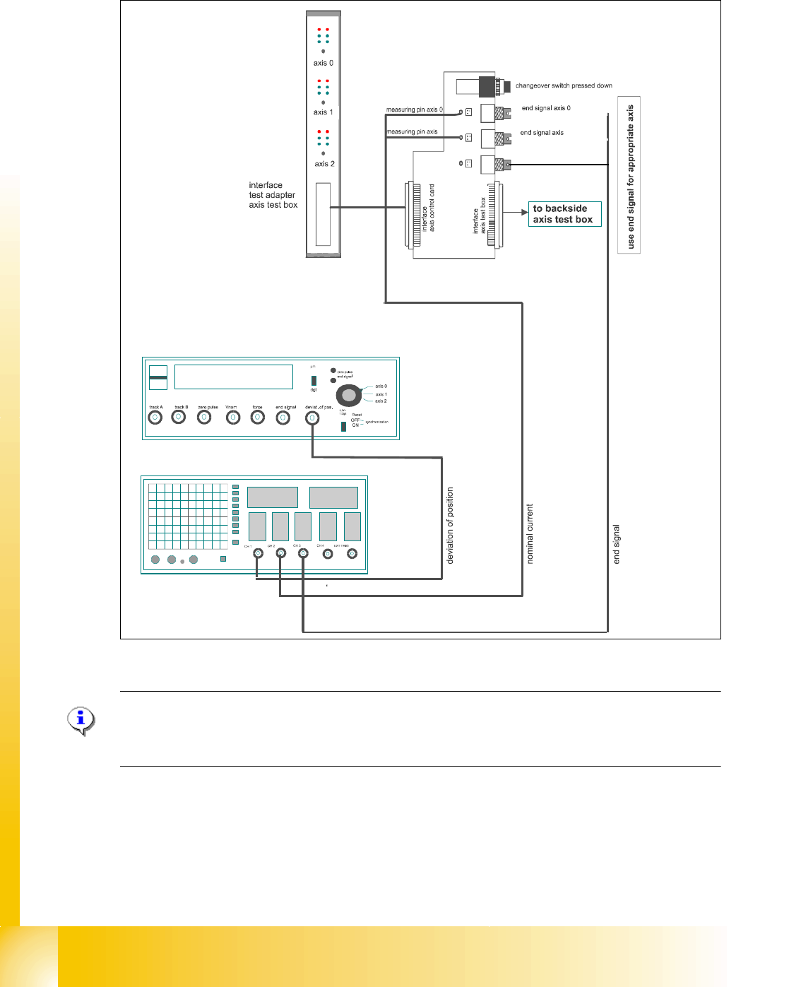
6.6.3.2 Test setup with axis testbox
Fig. 6.6 - 5 Test setup to check the axis dynamic signal ,
Please Note:
Use an RC - filter to record the current signal.
Measure the end signal on the adapter board "axis test box", with the switch pressed down. 6
11